This procedure covers installation, pressure testing and functional commissioning of firefighting sprinkler system.
Method statement covers an integrated system of underground and overhead piping designed in accordance with fire protection engineering standards.
This method covers portion of the sprinkler system above ground in a network of specially sized OR hydraulically designed piping installed in a building, structure, OR area, generally overhead and to which sprinklers are attached in a systematic pattern.
Valve controlling each system riser is located in the system riser or its supply piping.
The system is activated by heat from a fire and discharges water over the fire area.
Wet piping system is a sprinkler system employing automatic sprinklers attached to a piping system containing water and connected to a water supply so that water discharges immediately from sprinkler opened by heat from a fire.
SYSTEM COMPONENTS
- Network of pipes
- Zone control valve assembly
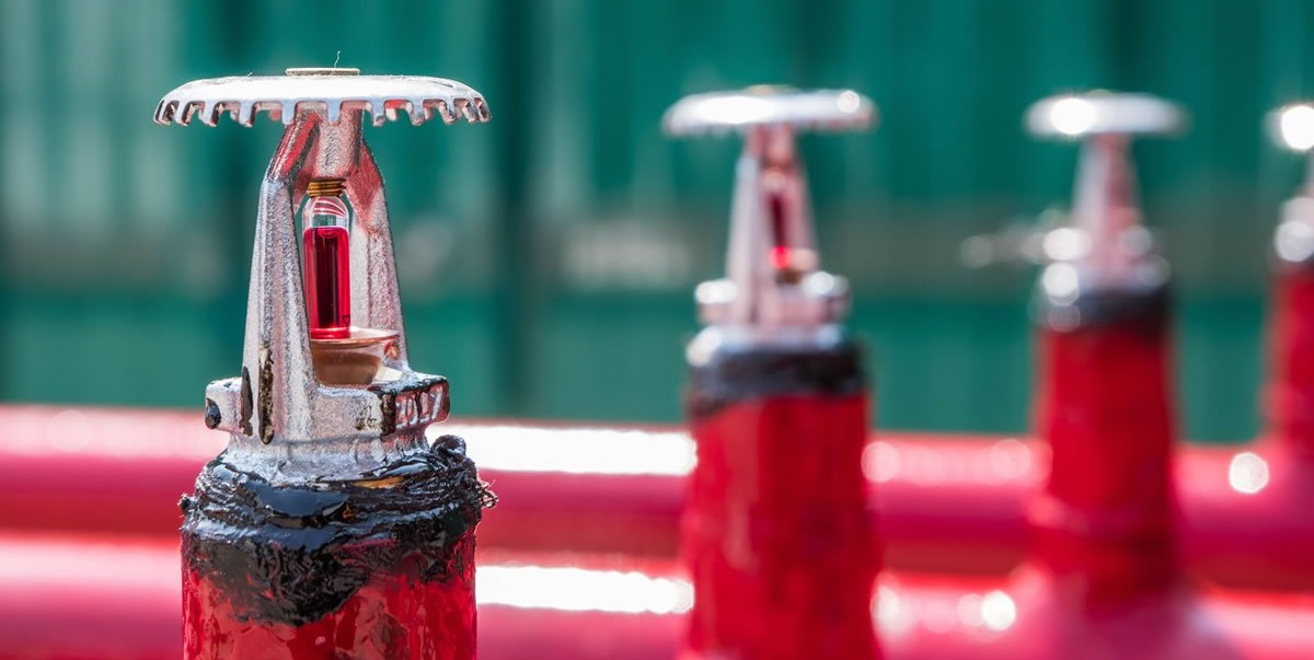
- Sprinkler
- Adjustable Spanner.
- Pressure Gauges.
- Pipe Wrench.
- Air release valve
- Fire Department Connection
- Minimum one four-way inlet breaching connection – to 2 1/2” fire hose and two-way inlet breaching connection to 1” fire hose reel system will be connected according to the accessibility to connect with fire department vehicle.
Quality of installation and materials at site will be ensured by project MEP team consisting of Project Manager, Project Engineer, QA/QC Engineer and the site Foreman.
Overall quality of the work will be according to the NFPA standards and local civil defense authority requirements.
Following tools and equipment will be used for fire sprinkler system installation:
- Grooving Machine
- Threading Machine
- Welding Machine
- HILTI Drill Machine Model TE-1 and TE-24
- 12” Grinding Machine
- Vice Table
- Pipe Wrenches
Supervision Responsibilities
Project Manager/Engineer:
Shall ensure that all the preparation and application works are carried out according to the contract specifications and manufacturer’s data sheets.
Also to ensure that the progressing of works is carried out according to the planned program and as per the approved method statement.
To ensure that all the equipment and material required for the execution of the sprinkler installation work are available according to the planned construction program.
Co-ordinate with the Main Contractor MEP Coordinator & Safety Officer for a safe and proper execution of the firefighting piping works.
To provide all necessary information and to distribute responsibilities to his construction/installation team.
Foreman will be responsible for the following :
Carry out his duties by maintaining continuous coordination with the project engineer on daily basis, to ensure proper distribution of the work force in the required and planned locations.
To provide to the project engineer a daily progress report indicating the works achieved and discuss with him the planned activities for the next day.
Make sure that daily work is progressing as planned and to advise the project engineer of any requirement for additional resources.
To be aware of test frequencies related to the pipe work and hydrostatic pressure testing.
Control disposal of waste materials according to the instruction received from the project engineer and hse department.
To ensure full coordination with the safety officers to maintain safe working environment and proper housekeeping of the site, following the approved safety measures and further ensure that all his working team are aware of the same to prevent accident and losses.
Inform the project engineer and QA/QC about the readiness of work for inspection and it’s checking, as applicable.
Installation of fire sprinkler system
The installation of fire sprinkler System shall be according to the approved detailed shop drawings and also as per the recommendations of NFPA 13.
Pipe hangers shall be spaced at intervals as specified in our approved shop drawing.
Threaded piping will be made with Teflon tape or with a suitable pipe sealing compound (jute and mastic combination) applied on male treads only.
Ends of pipe will be renamed out before being made up into fitting.
2” and below sizes of pipe are made threaded & 2 ½” and above sizes are normally grooved type.
Groove can be made cut groove or roll groove.
All underground fittings will be welded type, and all piping coming underground will be wrapped with polyvinyl chloride tape.
Firefighting piping must be rigidly supported by a combination network comprised of pipe hangers and rigid support brackets.
Pipe hangers are used to support the ‘dead load” of the pipe system.
Spacing will be as per the approved schedule.
Sprinkler heads shall be installed in accordance with approved system plans and coordinated RCP layout.
Installation of Sprinkler Heads
Sprinkler heads shall be installed according to current revision of NFPA 13 standard requirements.
System piping must be properly sized according to the approved drawings and calculation in order to achieve minimum required flow rate at each sprinkler head.
Install the sprinkler heads after the piping is approved and any other works are not required to avoid mechanical damage.
In the event of a thread leak, remove the unit, apply new pipe Teflon tape, and reinstall.
The face of the sprinkler fitting should be installed a nominal 3/8” to 1” behind the finished ceiling line, adjustment may be made via the push-on escutcheon plate to compensate for variation in the fittings.
Hand tightens the sprinkler into the fitting using the proper size of wrench.
To install the escutcheon plate, align it with and press it over the sprinkler body until the outer edge of the escutcheon meets the mounting surface
Installation of Butterfly Valve
Butterfly valve shall be installed and located as per the approved drawings, also to make sure that it is located where it will be readily accessible for operation, inspection and maintenance.
During installation make sure that the valve disc does not interfere with the operation of other systems components immediately adjacent to the butterfly valve.
When a valve “closes hard”, it may be due to debris lodged in the sealing area, this may be corrected by backing-off the hand wheel and closing it again, several times if necessary. The valve should never be forced to seat by applying a wrench to the hand wheel as this may distort the valve components or score the sealing surfaces.
Inlet and outlet piping adjacent to the valve should be properly supported to prevent excessive stress on the valve body.
The valve should not be used to force a pipeline into position as this may result in distortion of the valve body.
Installation of Flow Switch
The flow switch should be located as per the approved drawings, also to make sure that it is located where it will be readily accessible for operation, inspection and maintenance.
Flow switch may be mounted on a horizontal or vertical pipe.
On Horizontal pipe this should be installed on the top side of the pipe where it will be easily accessible.
Drain the system and drill a hole in the pipe using a circular saw in a slow speed drill, the whole size shall be 2”.
Clean the inside of the pipe from all growth or other material for a distance equal to the pipe diameter on either side of the hole.
Roll the vane so that it may be inserted in the hole; do not bend or crease it.
Insert the Vanes so that the arrow on the saddle points in the direction of the water flow.
Install the saddle strap and tighten nuts alternately.
The vane must not rub the inside of the pipe or bind in anyway.
Hydrostatic Testing of pipe line
- Plug all the openings
- Close all the drain valves.
- Fill complete pipeline with water avoiding any air column. (For this purpose keep the drain valve at the highest elevation slightly open, while filling water when line is completely filled with water close the valve)
- By using a pressure pump pressurize the line to an intermediate pressure, say 100 psi. Wait for 5 minutes; check all major joints for any visible leak.
- If the system is OK again pressurize the system to 150 psi and wait for 10 minute for any drop in pressure or leakage.
- If the system is found to be leak proof pressurizes the line to the required testing pressure and keep the pressure for 2 hours.
| Test Condition | Performance requirement |
| Test Pressure: 1.5 times of the working pressure
Duration: 2 hours under pressure Monitoring: By calibrated pressure Gauge installed at the lowest element |
No visible leakage from external piping.
At the end of 2 hours duration, there should not be any remarkable change in system pressure. |
Functional Testing for Sprinkler System
|
S. No. |
Test Description | Performance Requirements |
|
1. |
Open the test valve on Alarm Check Valve |
|
|
2. |
Open sure test valve |
|
|
3. |
By a heat source operate remote Sprinkler |
|
Sprinkler system Commissioning Procedure
The following are to be checked prior to handover of the Fire Sprinkler System to the Clients/ End Users.
All Sprinkler System Network and attached appurtenances subject to system working pressure shall be hydrostatically tested at 200 psi. (13.8 bars) and shall maintain that pressure without loss for 2 hours, loss shall be determined by a drop in gauge pressure.
Test the connection of the Tamper Switch of the Butterfly Valve by closing the valve to result a Fault signal on the Main Fire Alarm Panel. Re-open the Valve after the test is conducted.
Test the Water flow switch device by opening the test and drain valve to result in an alarm on the premises and at the Main Fire Alarm Panel. Close the Test & Drain Valve after the test is conducted.
Actual Discharge Test can be conducted; ( if required )
First Let another person wait at the Butterfly valve to close the system when receives the instruction to close the valve.
A Flame shall be brought near the Sprinkler Head which will result Breakage of the Glass Bulb in the Sprinkler head causing discharge of water from the head.
Check that there is a constant flow of water discharging from the open sprinkler head.
Keeps the water running until the Alarm Bell starts ringing in the premises? Measure the time between the Sprinkler discharge and the Alarm Activation.
Check that the Main Fire Alarm Panel has notified that the fire water sprinkler system is running at that particular area.
Close the Butterfly valve to stop the water from flowing.
Open the Test and Drain Valve to drain the system.
Re-place the broken sprinkler head with new one.
Close the Test & Drain Valve.
Open the Main valve to allow water to fill the Sprinkler System network piping again.
When a steady flow of water is running through the pipe without air bubbles (to ensure that the system pipe work have been flushed and that the air inside the pipe network is taken out), close the valve and normalize the system.
Discover more from Method Statement Store
Subscribe to get the latest posts sent to your email.