This method statement covers installation and inspection of 1” Fire Hose Reel System and 1 ½” Fire Hose System which is part of overall firefighting system.
Purpose of this method of statement is to define the method of installation and inspection of Fire Fighting Hose Reel System.
Quality of installation and materials at site will be ensured by project team consisting of a Project Manager, Project Engineers, QA / QC Engineer and the site Foremen.
Work shall strictly follow as per the Manufacturer’s/ Client’s / Consultant’s Health & Safety recommendations for handling and use of the materials.
Contractor shall ensure that all involved personnel are aware of the relevant health safety and environmental HSE requirements and control measures.
All the installation work will be according to the project specifications, NFPA standards and /or local civil defense authority requirements.
Necessary Tools & Equipment
The following Tools and Equipment will be used for Fire Fighting System Installation:
- Grooving Machine
- Threading Machine
- Welding Machine
- Drill Machines ( Hilti Models TE-1 and TE-2 Type)
- 12” Grinding / Cutting Machine
- 4” Grinding Machine
- Vice Table
- Pipe Wrenches & Spanners, etc.
Fire Fighting System Description
Fire Hose Reel- Automatic Wet System: It is a system that is attached to a water supply capable of supplying the system demand at all fires and that requires no action other than opening a hose valve to provide water at hose connection.
System Components
Network of pipes
Fire hose & fire hose reel cabinets
Landing Valves
Pressure reducing valves
Air release valve
1” Fire Hose Reel & 1 1/2” Fire Hose System considerations:
Surveying
– Area per floor occupancy
– Distance of the hose connection from the source(s) of the water supply
– Number of floor levels
– Means of escape/exit passage way
Location of Landing Valve / Hose
– At each intermediate landing between level
– On each side of the wall adjacent to the exit opening
– Exit passage way at the entrance
– As per approved shop drawings.
Minimum pressure of stand pipe
- Hydraulically designed to provide 10 GPM (37.85 liter per minute lpm) at a minimum residual pressure of 2.2 bars at the outlet of the hydraulically most remote 1” dia. hose reel connection.
- Hydraulically designed to provide 100 GPM (378.5 liter per minute lpm) at a minimum residual pressure of 4.5 bars at the outlet of the hydraulic most remote 1 1/2” dia. Fire hose connection.
Material Storage and Handling
The firefighting pipes will be stacked in the site store on a flat surface at a height not exceeding 1.7 meter from the bottom layer.
All the fittings will be separately packed and stored as per the sizes required for the project.
Open ends of pipes will be covered to protect from foreign matters, dirt, debris etc.
General Piping Installation Guidelines
Fire hose reel piping shall be installed in accordance with the piping general arrangements and their supporting drawings, specifications and schedules.
Installation of pipe work shall be carried out under conditions satisfactory to the main contractor and consultant.
All work performed and completed must meet the approval of the contractor, consultant and client.
Scheduling of work to carry out the installation of fire hose reel pipe work shall be agreed and to the satisfaction of the client and shall be co-coordinated with the work schedules of other trades and disciplines involved in the overall construction activities at the project.
Sequence of Work for Installation of Hose Reel System Piping
Run all piping as direct as possible, avoiding unnecessary offsets and conceal piping in finished rooms.
2” and below sizes of pipes are made threaded, 2 ½” and above sizes are normally grooved type.
Groove can be made Cut groove or Roll groove, it is recommended to make Roll Grooves utilizing manufacturers Roll Grooving Tools.
Make tee connections with standard tee fittings for full size branches.
All piping must be rigidly supported by a combination network comprised of pipe hangers and rigid support brackets.
Pipe hangers are used to support the “dead load” of the pipe system.
Pipe hangers will be spaced according to the relevant NFPA standard / Specification clause.
Hanger rod sizes and numbers will comply with the requirement of the respective NFPA standard / Specification clause or Manufacture’s recommendations.
Installation of Fire Hose Reel / Fire Hose Cabinets
Before installation check that the cabinets are of approved size and dimension, also inspect for signs of any damage. If damaged should be replaced by new one.
Locate exact location of the Cabinets as per approved shop drawings and with careful measure of elevation and plumb.
Fix cabinet using recommended Rawl (anchor bolts) bolts.
Proceed with installation of accessories, lock shield valve, landing valves, etc. taking in consideration of approval for these devices.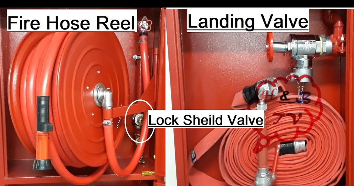
Installation of Breaching Inlet
Locate breaching inlet cabinet and its accessories as shown on the shop drawing near the main entrance of the building for Civil defense to inject water into the system in case of emergency.
Install the cabinet using approved accessories to the satisfaction of the client/consultant.
Method of Threaded Joints
Threaded piping will be made with Teflon tape or with a suitable pipe sealing compound (jute and mastic combination) applied on male threads only.
Ends of pipe will be reamed out before being made up into fittings.
Joints in threaded steel pipe will conform to the American National taper pipe thread, ANSI B1. 20.1 Or British Standard BS 21.
All burrs will be removed, pipe ends will be reamed or filed out size of bore, and all chips will be removed.
Pipe Fabrications and Installation
Make piping layout and installation in the most advantageous manner possible with respect to headroom, valve access, opening and equipment clearance, and clearance for other work, particular attention will be given to piping in the vicinity of equipment. Make sure to preserve the equipment parts for maintenance.
Cut all pipes accurately to measurement determined at the site. After cutting the pipe, ream it and remove all burrs.
Install piping neatly, free from unnecessary traps and pockets.
Work into place without springing or forcing.
Use fittings to make all changes in direction.
Make all connections to equipment using flanged joints or unions.
Make reducing connections with reducing fittings only.
Remove dirt, scale and other foreign matter from inside piping before tying in sections, fitting, valves or equipment.
Offsets and Fittings Installation
Carefully investigate the structural and finish conditions affecting the work and take such steps as may be required to meet such conditions.
Install all piping close to walls, ceilings and columns so piping will occupy the minimum space.
Proper space will be provided for covering and removal of pipe, special clearance, and for offsets and fittings.
Pipe work will be installed not closer than 200 mm to electrical conduits, lighting, and power cables.
Firefighting pipes will be spaced in ducts, ceilings, voids and plant areas, such as adequate access is permitted to any pipe for maintenance or removal without disturbance to the remaining pipe work and other services.
Pipes will not be solidly built into walls or plaster.
Pipe joints will not be positioned within the thickness of walls, floors or in any other inaccessible position.
All the pipes passing through walls and floors will be sleeved; where they are exposed to view chrome plated covers will be fitted.
Couplers, unions and fittings will be screwed up to the reduced depth of the thread, such that no more three-turns are showing when pulled up tight.
All pipes, valves and fittings and connected equipment will be thoroughly cleaned of rust, sand and dust, scale and other foreign matter before erection and before any initial fill water for hydraulic testing.
Prior to hydraulic testing, all pipe work systems including valves, strainers and fittings will be washed thoroughly.
Any washing of the piping systems will be carefully carried out where there are isolation valves or equipment are employing.
Any stoppage due to foreign matter or air lock which is found to impede the flow of fluid will be removed, either before or after the systems are in operation.
Fittings will be of the eccentric pattern to ensure proper drainage and the elimination of air pockets wherever necessary.
Increases or decreases in pipe diameters required to suit fittings, tee-offs and equipment connections will be formed using taper pieces, flange as required with taper reduction located about axis of the pipe to facilitate proper flow and to allow proper venting and draining of the pipes.
The angle of the taper of such fabricated taper pieces will not be greater than twenty (20 ▫) degree.
Painting of Fire Fighting Piping
All pipes will be cleaned inside and outside for removal of dust and debris before painting.
One coat of Approved Red-oxide Primer will be applied of 35 Microns film thickness.
After drying of red oxide one coat of Approved Enamel Paint will be applied of 35 Microns film thickness before installation of pipe.
Finally one coat of Approved Enamel Paint of 35 Microns will be applied after hydraulic test and in the final stages.
Flushing: Cleaning of Piping and Equipment
After piping is erected, all piping systems including main header line and branch line will be cleaned to remove all mill, welding scale, oil, corrosion, and other construction debris.
Automatic devices which can become clogged during the cleaning process will be disconnected and will not be connected permanently until the cleaning process is complete.
System will be flush cleaned and filled ready for service immediately after cleaning.
Do not operate pumps or equipment until debris are removed from the respective piping system and it is completely flushed out.
Flushing of the system can be done from a pumping source with minimum flow rate to provide a velocity of 3 m/ sec.
Flush the firefighting piping system until all debris are removed and clean water comes out.
Discover more from Method Statement Store
Subscribe to get the latest posts sent to your email.