This specification document covers uninterruptible power supply UPS system Supply, installation, testing and commissioning of capacities as shown on the related drawings.
The UPS system shall operate in conjunction with the building electrical system and the generator to provide high quality power for critical equipment loads such as data and computer servers and related equipment, power outlets feeding main controllers of security system, etc. for a period of 30 minutes until the generator power is available.
This will hereafter be referred to as the “UPS”, and shall provide continuous, regulated AC power to the loads under normal and abnormal conditions, including loss of the utility AC power.
The UPS shall be completely solid-state except for maintenance bypass switches which may be mechanical.
All UPS shall have interface cards to have the following and shall be complete with system software:
- Required input and output dry contacts for reporting alarm and status.
- RS232 port for serial communication for advanced remote monitoring and control through computer network.
- Communication port with appropriate protocol for connection to BMS system.
All UPS systems shall be based on latest IGBT (insulated Gate Bipolar Transistor ) technology with PWM (Pulse Width Modulation). Rectifier configuration shall be such that THDI (Total Harmonic Distortion Current) at upstream shall be minimum.
Factory testing documentation shall be furnished along with the equipment.
The UPS shall be installed in accordance with the manufacturer’s recommendations.
Quality Assurance Requirements
The UPS shall be manufactured under quality assurance in accordance with ISO 9001, manufacturer shall have a quality assurance program with checks on incoming parts, modular assemblies and final products.
UPS shall be tested at full rated load without failure for a minimum of 24 hours.
A final test procedure for each UPS shall include a check of performance specifications before and after the 24-hour full load test.
An on-site test procedure shall include a check of controls and indicators after installation of the equipment.
The UPS shall be designed, manufactured and tested in accordance with the applicable portions of the following standards:
Safety: EN50091-1, IEC-62040-1-1
EMC: EN50091-2, IEC-62040-2-0, IEC61000-3-4 & IEC-61000-4-2
Performance standards: EN50091-3, IEC-146-4 and 146-5
Marking: CE, TUV/GS
Design Production Logistics & Service: ISO 9001
Applicable local laws and regulations
Environmental Conditions
The UPS system shall be capable of withstanding any combination of the following environment conditions in which it must operate, without mechanical or electrical damage or degradation of operating characteristics:
a) Ambient temperature: 0 to 50 degrees C.
b) Relative humidity: Up to 95% (non condensing)
c) Interference: The UPS equipment shall be provided with EM/RFI suppression following EN-50091-2/IEC 62040
Technical Submittals
Catalogue cuts and/or data sheets describing the proposed equipment shall be submitted.
A user’s listing shall be furnished giving company names, locations and UPS models installed.
All deviations to this specification shall be listed and included with the submittal.
A minimum of three sets of submittals shall be sent to the Consultant.
Submittal shall also include the battery sizing calculation.
One certified copy of the factory test reports shall be furnished.
After Installation of Equipment: Three operations and maintenance manuals shall be furnished and shall include as a minimum the following:
- General information
- Safety precautions
- Installation instructions
- Operating instructions
- Maintenance and troubleshooting guidelines
- Recommended spare parts list.
A signed service report describing start-up and on-site testing shall be furnished after start-up of the equipment.
Spare parts required for initial start-up and commissioning shall be provided to the Consultant.
UPS System Components Requirements / Specifications
This specification describes a continuous duty, solid state, uninterruptible power supply system, hereafter referred to as the UPS.
The UPS shall operate in conjunction with the building electrical system and the generator to provide high quality power for critical equipment loads.
UPS system shall consist of an inverter, rectifier/battery charger, storage battery, a static bypass transfer switch, synchronizing circuitry, an internal maintenance bypass switch, Cooling fan, inlet dust filter etc. and shall have isolation transformer in the bypass line.
Unit Rating
The rated output of the UPS shall be based on standard duty Class II of IEC publication 146.
UPS shall have 3-phase and neutral output.
The neutral of the A.C. output shall be earthed.
It shall be of VFI (Voltage and Frequency Independent) Technology to EN 50091-3.
The UPS unit shall be rated to continuously energize the load at a load power factor of 0.8 lagging while maintaining an output voltage at the terminals of the unit within the permissible tolerances, and while satisfying the operation requirements specified in this document.
UPS unit shall also be capable of energizing, within its kW/kVA rating, similar loads having power factors between 0.7 lagging and unity, while operating within the specified tolerances.
UPS Electrical Loads
The electrical loads energized by the UPS shall comprise principally of electronic equipment, IT equipment, server, etc.
Electrical Characteristics:
a) Rectifier Input
Voltage: 415V AC 3 phase, earth
Admissible Voltage Variation: + 15% to -25%
Frequency: 50 Hz +- 20%
Input THDI at full load: <3%
Input Power factor: Greater than 0.99
b) Inverter:
Output Voltage: 415V AC, 3 phase Neutral and earth
Voltage Tolerance: + 1%
Frequency: 50 Hz +- 0.01%
Power factor: 0.8 to unity
Total harmonic distortion downstream (THDV): <5% for non linear loads and 1% for linear loads
Overload Capacity: 125% for 10 minutes, 150% for 1 minute
Crest Factor: 3:1 or better
Efficiency : >94%
Limitation of harmonics at upstream of the UPS:
UPS system shall not draw a level of harmonic currents that could disturb the upstream AC system.
It shall comply with the relevant standards and shall be in accordance with Local Electricity Authority requirements. However it shall not be greater than 3%.
THDI (Upstream) < 3%.
It shall be achieved using suitable configuration of rectifier circuits (IGBT, 12 pulse, etc.), and other advanced technology system components from manufacturer standard product range.
The extremes of voltage and frequency variations are not to be considered to coincide.
Inverters shall not changeover to their bypass supplies during any one transient as defined above.
In addition to the above variations, the input voltage may be subject to transient comprising of voltage depressions up to 20% of the nominal voltage during motor starting, and to voltage interruptions during system short circuits.
Transient, high frequency voltages of up to 2 kV may also be superimposed on the input voltage as a consequence of system switching operations etc.
UPS Configuration and Tie-in
Cables connecting the batteries to AC UPS units shall be single core, flexible, 600/1000V grade EPR insulated. These shall be sized and supplied by UPS supplier.
A suitable molded-case circuit breaker shall be provided with the UPS unit to facilitate on-load isolation of the battery for the purpose of performing battery maintenance.
Molded-case circuit breakers shall be category B, in accordance with IEC 947-2.
The switching device shall be installed adjacent to the battery, inside the battery room.
A manual bypass switch, make before break, shall be provided to enable the load to be connected to the bypass circuit.
The manual bypass switch shall at the same operation disconnect the inverter and static changeover switch to ensure safe operating conditions for maintenance purpose.
A warning label shall be provided to warn the operator against operating the manual bypass switch if the “out of synchronization” warning indicator is showing.
Isolation of the inverter shall only be possible if an alternative supply is connected to the load bus.
The UPS should have a separate enclosed Isolation Transformer in the bypass and the output rating shall match the inverter output rating.
The transformer shall be a double wound air cooled type with an earthed screen between the primary and secondary windings.
Rectifier
The rectifier shall be IGBT/12 Pulse based with DSP / microprocessor controlled type as per manufacturer’s standard product range.
Batteries shall be valve regulated sealed lead acid type with 12 years service life unless specified otherwise.
The rectifier design shall include charge voltage compensation for the battery operating temperature.
This is to ensure that the recommended minimum and maximum charge voltages are maintained over the operating temperature range to achieve optimum battery service life.
Rectifier shall operate according to the constant voltage, current limiting principle and shall incorporate a ‘soft-start’ feature to gradually accept load on initial energizing.
The rectifier shall restart automatically upon restoration of the mains power supply following a mains supply interruption.
The rectifier shall be rated to simultaneously:
- Fulfill the inverter input requirements when the inverter is delivering its rated output at 0.8 power factor lagging.
- Recharge the battery, within a period of 8 hours, from the partially discharged condition to a capacity that will enable it to fulfill the inverter input power requirements, for the duration as specified hereafter when the inverter is delivering rated output at 0.8 power factor lagging.
The above recharge performance shall be achieved irrespective of the type and method of battery recharging employed.
Rectifier shall perform battery charging only at the single-rate corresponding to the battery float-charge mode of operation.
No rapid-charge facilities shall be provided.
Switched diodes or supplementary battery cells as a means of limiting D.C. voltage variations are not acceptable.
The D.C. supply shall not be utilized to energize loads other than the inverter.
Battery Float-Charge Operation
The rectifier steady-state D.C. output voltage variations shall be controlled to within plus 1% and minus 1% of the set value (corresponding to the battery float-charge voltage) during load variations between zero and the rated output of the rectifier, and during steady-state input voltage and frequency variations specified.
Short-time mains supply voltage depressions of not more than 20%, which may be the result of motor starting activities, shall not result in a trip of the rectifier or the initiation of battery discharge.
On-line adjustment of the set value of float-charge voltage shall be possible by means of LCD settings and/or by an appropriate menu driven software change.
The D.C. output current of the rectifier, when operating under constant current limiting conditions, shall be controlled to within plus 2% and minus 2% of the set value.
Battery and D.C. Circuit
The battery voltage and capacity shall be such as to fulfill the inverter input power requirements when the inverter is delivering its rated kVA output at 0.8 power factor lagging, for the duration of 90 minutes.
The battery discharge performance shall be fulfilled:
Throughout the range of service conditions specified, including that corresponding to the minimum cell temperature specified.
Repeatedly, each discharge performance being preceded by restoration of the battery to the required capacity by means of a recharge operation not exceeding eight hours, following a prolonged period (i.e., not less than one year) of battery float-charge operation.
The nominal ampere-hour capacity of the battery supplied with the UPS shall include all necessary allowances required to compensate for aging effects that result in the progressive loss of capacity.
However, the nominal ampere-hour capacity of the new battery shall be not less than 110% of the nominal ampere-hour capacity required to fulfill the performance criteria stated above.
The UPS shall be capable of energizing loads between zero and its rated output, and of performing load transfer switching, in accordance with the requirements of this specification, without the battery being connected.
The current ripple limits specified by the battery MANUFACTURERS, for the battery supplied with the UPS, shall not be exceeded during at least normal standby operating conditions.
Inverter
The inverter shall be transistorized (IGBT) type PWM (Pulse Width Modulated) with DSP/microprocessor based controls.
Inverter shall be of the current limiting type (short circuit proof) and have nominal output voltage and frequency as specified.
The inverter output voltage and frequency shall not exceed the operational tolerances, as measured at the output terminals of the unit, during the following conditions of UPS loading:
Load variations between zero and the rated output of the UPS
Load power factors over the range 0.8 lagging to unity.
Load current waveform having a relative harmonic content varying between zero and 50%, the latter waveform having a crest factor not exceeding 2.5 and individual harmonics not exceeding the following values:
3rd harmonic 44% of fundamental
5th harmonic 33% of fundamental
7th harmonic 18% of fundamental
9th harmonic 7% of fundamental
11th harmonic 10% of fundamental
D.C. input voltage over the range corresponding to battery rapid charge and battery discharge operation during the specified discharge times.
The inverter shall control the output voltage of the UPS such as to maintain synchronism with the mains bypass voltage during variations in mains frequency up to the limits specified.
During variations in mains bypass frequency exceeding these limits, the inverter shall revert to internal frequency control.
Automatic synchronizing to maintain output frequency within +/-5 degrees of the external reference signal, (provided the reference frequency stability is within +/- 1 Hz), shall be supplied.
Upon failure of this reference, the inverter shall maintain the frequency within the tolerances quoted until the external reference returns.
The inverter shall then automatically re-synchronize to the external reference.
Rate of frequency change during synchronizing shall not exceed 0.1 Hz per second when changeover is by the static switch.
Loss of synchronizing signal between the inverter and the bypass supply shall:
- Not block automatic actuated transfers from normal to bypass supply.
- Not block automatic actuated transfers from bypass to normal supply.
- For solid-state transfer switches, block manually actuated transfers to either supply.
Output Voltage Static Regulation
The output voltage static regulation shall be maintained within plus 2% and minus 2% of rated output voltage.
When the load current in any two phases differs from the rated output current by up to 50%.
Output Voltage Dynamic Response
Dynamic output voltage variations shall not exceed plus 10% and minus 10% of rated output voltage in the event of instantaneous load changes of 100% rated output.
The output voltage shall be restored to within the steady state limits of plus 5% and minus 5% of rated output voltage within 0.1 seconds.
Frequency Deviation
The frequency of the output voltage shall be maintained within plus 0.01% and minus0.01% of rated frequency when operating on internal frequency reference.
Output Voltage Waveform
The waveform of output voltage shall be sinusoidal.
Inverters shall provide power from zero to full rated output without exceeding the specific 4% total harmonic distortion of the output voltage wave shape.
The load typically includes nonlinear loads which can introduce harmonics in the inverter output current.
Inverters shall be capable of supplying the load without sustaining damage to any of their components due to such harmonics.
Output Voltage Symmetry
The angular displacement of the phase voltages shall not exceed 120° ±1% when supplying a balanced, linear load at rated output, 0.8 power factor lagging, and 120° ±1% when the load current in any two phases differ by 50% from the rated output current.
Short Circuit Current
The inverter shall be capable of delivering sufficient short circuit current to cause main output circuit fuselinks /circuit breakers, rated nearest to 10% of the UPS rated output current, to interrupt the short circuit current within 3 millisecs when the UPS is not synchronized with the mains bypass supply.
The main output circuit fuselinks shall be of the slow-acting type g1, in accordance with IEC 269.
Static Bypass Switch
Circuit Rating
The load transfer switching devices may comprise of either continuously rated static elements in both inverter and bypass circuits, or continuously rated electromechanical switching devices with short-time rated static elements.
Bypass circuit shall have a continuous current rating equivalent to the rated output of the UPS unit and be capable of conducting a current of ten times the rated output for not less than two seconds.
In view of electronic components involved, reliability in terms of high Mean Time between Failure (MTBF) factors is essential.
To achieve this objective, manufacturer is required to examine the rating factors applied to all components used in manufacturing, and guarantee that the ratings for this application will be modified as necessary to ensure long term reliability.
Load Transfer Criteria
Facilities shall be provided to manually and automatically initiate transfer of the load from the inverter to the bypass circuit, and from the bypass circuit to the inverter.
The combined detection and switching time required to transfer the load from the inverter to the bypass circuit in the event of instantaneous loss of inverter output voltage shall not exceed 0.5 millisecs.
When the inverter is running with its internal reference frequency and the static switch is blocked, any failure of inverter shall initiate a transfer to bypass supply after a time delay which can be adjusted from 50 to 500 milliseconds.
Transfer of the load from the inverter to the mains bypass
The criteria for load transfer shall be as follows:
Load transfer shall only be possible when:
- The mains bypass voltage is within ±15% of rated UPS output voltage.
- Mains bypass frequency is within the tolerances specified.
- The inverter output and mains bypass voltages are synchronized.
Automatic transfer of the load shall be initiated when:
The inverter output voltage drops below 95% of the nominal output voltage.
Transfer should be accomplished before the voltage reaches 85% of the nominal value, or inverter output voltage exceeds 105% of the nominal output voltage.
Transfer should be accomplished before the voltage reaches 115% of the nominal value.
The inverter output current limit is exceeded.
Retransfer of the load from the mains bypass to the inverter.
Load retransfer shall only be possible when:
The inverter output voltage in within ±10% of the nominal output voltage for more than 5 seconds, and The inverter output and mains bypass voltages are synchronized.
Subject to fulfilling the above criteria, retransfer of the load from mains bypass to the inverter shall be initiated automatically following automatic transfer of the load from the inverter to the mains bypass.
The automatic retransfer of the load to the inverter shall be inhibited following four automatic transfers of the load to the bypass, if these take place within an interval of 5 minutes.
An annunciation shall be provided under this condition.
Subject to fulfilling the above criteria, automatic retransfer of load back to the inverter(s) from the bypass shall operate as follows:
A two-position “AUTO-STANDBY” retransfer selector switch shall be provided for each changeover switch to control the automatic retransfer operation.
When the retransfer selector switch is in the “AUTO” position, retransfer back to the inverter supply shall occur automatically whenever the conditions above are met.
When the retransfer selector switch is in the “STANDBY” position, retransfer back to the inverter supply shall occur automatically only if the bypass supply has been lost and normal voltage is present on the inverter supply.
All transfer switches and the actuating devices for these controls shall be so located or guarded to prevent accidental operation.
Noise Limits
EEMUA Specification No. 140: ‘Noise Procedure Specification’, formerly OCMA NWG-1, shall be adhered to with regard to definitions, notations, measuring equipment, procedures, reporting and calculation methods.
The sound pressure level measured at one meter distance form the UPS unit, at any position, shall not exceed 65 dB(A) at any load between zero and the rated output of the unit.
If tonal components are present, the noise limit shall be 5 dB(A )less.
In the event that more stringent limits apply, these will be indicated in the requisition.
The manufacturer shall submit the guaranteed sound power levels and/or sound pressure levels of the equipment, together with any other relevant information, as requested in the requisition.
If the above values are unobtainable without the use of absorptive materials, precautions shall be taken to limit their effect on cooling, dust depositions and fire hazards.
Radio Frequency Interference Limits
The production of radio frequency interference voltages shall not exceed the values of suppression grade ‘N’, as defined in VDE 0875 and EN 50091-2.
Performance of the UPS unit shall not be affected, or in any way degraded, by the use of portable radio transmitters/receivers operating in the frequency range 27-170 Mhz, at 460 Mhz, and at 800 Mhz when the severity of the electromagnetic radiation environment corresponds to Class 2, in accordance with IEC 801-3 /IEC 62040-2.
UPS System Construction Requirements
Unit Enclosure
The rectifier, inverter and static switch shall be installed in one or more freestanding, self-supporting steel cabinets forming an enclosure.
Each cabinet shall be suitable for operation and maintenance with its rear panel against a wall and with similar units located immediately on both sides.
All cubicles and equipment shall be fully tropicalized.
Enclosure protection shall be not less than IP20 per IEC 529, without considering the floor as part of the enclosure.
Each cubicle shall be fitted with breaker which can be operated externally.
With the breakers in the “off” position the unit shall be fully isolated for maintenance purposes.
Any live terminations which cannot be isolated such as bypass supplies, which must remain “on” to maintain the supply to the load, shall be fully shrouded and adequate warning markings fitted. The terminals shall, as far as possible, be segregated from the isolated circuits.
The distribution section shall be provided within a cubicle unit.
The number of ways and the rating shall be as detailed in the data sheets or single line diagram.
Cooling Requirements
Internal cooling of the unit shall be by natural or forced air ventilation.
The unit shall be capable of continuously delivering its rated output with any one forced air ventilation fan out of service.
Under the latter conditions, the maximum continuous temperature of components shall not be exceeded.
The unit shall not incorporate cooling air filters that require periodic cleaning and/or replacement.
Accessibility Requirements
Equipment and components located within the enclosure shall not be mounted directly on the walls of the enclosure.
The location and grouping of components and auxiliary equipment shall permit easy identification and access for operational, maintenance and repair purposes.
Suitable partitioning between individual items shall be provided where necessary to allow adjustment and inspection to be carried out safely.
All live terminals of door-mounted equipment having a maximum (peak) voltage of greater than 24 volts shall be shrouded on otherwise protected by barriers to a degree of protection of at least IP30.
Barriers shall be of rigid transparent insulating material to enable the screened components to be identified.
Protection relays which can cause tripping of the unit shall not be mounted on the door.
All bare busbars and all live terminals of equipment and components located within the enclosure shall be similarly protected by barriers or shrouds to a degree of protection of at least IP 20, unless adequately recessed within the enclosure to prevent inadvertent contact or short circuit by personnel when performing control circuit adjustments or when resetting/replacing protective devices etc.
Battery Enclosure
Batteries shall be installed on freestanding support racks in a separate battery room.
Battery enclosures shall be naturally ventilated to disperse gaseous products.
The battery shall be positioned such that possible leakage of electrolyte or emission of gaseous products shall not cause damage to other equipment, components, or adjacent cells.
Separate, freestanding support racks for batteries having plastic cell containers may be steel or solid wood.
All wood should be retreated to render it non hygroscopic and acid resistant.
Steel racks shall have a plastic or epoxy coating to provide suitable protection against the effects of electrolyte spillage.
Converter Components
Printed Circuit Boards (PCB) shall be installed in standardized electronic equipment frames and be fitted with handgrips for easy removal.
The frames shall incorporate card guides to facilitate the correct insertion of PCB’s, and allow access to the wiring side of connectors.
PCB’s shall include visual LED status indications and test connections on the front to facilitate fault diagnosis.
Main circuit switches (mechanical) shall comply with IEC 408 and be of the independent manually operated air-break type of continuous duty. They shall comply with utilization category AC23 and DC23 for A.C. and D.C. switches respectively.
Contactors shall comply with IEC 158-1 and be rated for uninterrupted duty and intermittent duty of at least Class 0.1.
The utilization category for D.C. contactors shall be not less than DC-4 and for A.C. contactors not less than AC-3.
Transformers and reactors shall be of the air-cooled type and comply with the relevant parts of IEC 146.
UPS Wiring and Terminations
Internal wiring shall be single core, 600/1000V grade PVC insulated, and have stranded copper conductors.
Conductor size for Power circuit shall be 2.5 mm2.
Wiring between terminals shall be continuous and without joints.
Wires shall be held in position by means of insulating tubes, channels, cleats or plastic strips, and be routed such as to avoid mechanical damage.
Wiring between fixed portions and hinged doors shall be mechanically protected against abrasion or entrapment and not be carried over or bent around sharp edges.
Individual wires or scales terminating in fixed (non plug-in) components which require to be disconnected for the purpose of component testing or replacement shall be identified by means of color or by ferrules of insulating material marked in accordance with the manufacturer drawings.
Terminals shall be provided for all external connections.
External connections shall not be made directly to component terminals.
Terminals shall be of the rail mounted type and have screw connectors suitable for a minimum of 2.5 mm2 conductors.
Only one conductor shall be terminated in each terminal.
Links shall be provided where more connections are required at one point.
Insulating shields shall be used to separate terminals belonging to different circuits.
For control wiring, pre-insulated crimped terminals shall be used and for power wiring crimped lugs with heat shrink Pre-shrouds shall be used.
Additional load circuit terminals shall be provided to facilitate connection of a temporary load to test the UPS unit while the permanent load is energized via the external bypass circuit.
The UPS enclosure shall have facilities for the entry of cables from above or below, as specified in the requisition.
Cable entries, cable glands and terminals shall be suitable for the type and size of cables shown in the single line diagram.
Cable glands shall be of the compression type and mounted on a removable gland plate.
The proximity of terminals and gland plates shall be such that ample space is available for terminating the cores of external cables.
Earthing Requirements
An earth rail, with a suitable number of earthing bolts or screws, shall be provided in a position close to the external cable glands to facilitate termination of cable earth braids or armoring.
Individual connections for all earth wires shall be provided.
A threaded brass earth stud of not less than 6 mm diameter, with nuts and spring washers, shall be provided within the enclosure to facilitate termination of a separate, single-core, earth cable.
Electrical conductivity between the exposed, non current carrying conductive parts of the UPS unit components and the enclosure, and between the enclosure and the earth rail/earth stud, shall be such as to maintain effective continuity of protective circuits.
Earth bonding conductors shall be utilized between enclosures and doors, and where required to achieve effective protection.
The neutral of the inverter output shall be earthed by a connection to the earth rail/stud within the enclosure.
Battery Cells and Containers
The batteries shall be VRLA type with 12 years life.
Cell containers of plastic material are preferred subject to the material being non flame propagating and mechanically shock resistant.
Protective covering to prevent inadvertent short circuiting.
VRLA battery cells are delivered and filled charged.
These cells must receive a commissioning charge within 3 months of leaving the factory.
Air-freighting of cells shall be considered as an alternative to delivery by sea-freight if the above commissioning requirements cannot otherwise be met.
Care shall be taken to store the VRLA batteries at site in air conditioned rooms.
During installation and thereafter battery room temperature shall be maintained not exceeding 25°C.
Marking
All external operating, measuring and indicating components shall be clearly identified with permanent descriptive labels that facilitate easy recognition by the operator.
All components shall be identifiable by labels inscribed in accordance with the system of identification used on the manufacturer reference drawings and documents.
Rail mounted terminals of equipment and components shall be identifiable by numerical or alphabetical markings in accordance with the drawings.
Terminals of input and output supply cables shall be clearly and uniquely marked to indicate the nominal system voltage and the phase/polarity of the supply. The identification of terminals shall be in accordance with IEC 445.
The following information shall be inscribed on a nondestructive, corrosion-resistant, indelible name/rating plate attached to the unit enclosure:
- Purchaser’s order number and equipment No.
- Year of manufacture
- Name of Manufacturer
- Type and serial number of unit
- Weight of cubicle
- Dimensions of cubicle
- Nominal input current and voltage
- Nominal output current, voltage and frequency
All labels/nameplates shall be of corrosion resistant material (3 ply white black white Trafolyte) with indelible inscriptions in the English language fixed by stainless steel screws or rivets.
All switches, instruments (meters), transformers, fuse holders, push buttons and indicating lamps shall have labels fixed adjacent to them.
The label shall carry a functional description and all essential data including, but not limited to, the following information as applicable:
- Fuse size
- Ratings (voltage, current, frequency);
- Accuracy (instruments)
- Switch duties
Finish
The treatment and protection of metalwork may be in accordance with manufacturers standard but shall include cleaning, degreasing, rust resisting primers and paint finishes that provide effective protection against corrosion under the functional and climatic conditions specified.
Color shade shall be green RAL 6021.
Mimic
Each unit shall have front of panel Mimic/Graphic Diagram showing all major components.
Measurement, Protection and Control Equipment
The UPS unit shall incorporate all the necessary equipment to enable operation, protection and control of the UPS in accordance with this specification, and to safeguard the unit and its components from the consequences of internal and external short circuits, over voltages and any main or control circuit malfunctions, howsoever caused.
Operating, status and diagnostic indications of light-emitting diodes (LED’s) or liquid crystal displays (LCD’s) shall be provided.
Each LED/alarm circuit shall have built-in test facilities. Failure of an LED/LCD shall not cause UPS maloperation or affect the correct functioning of the remote common alarm signal.
Indication by means of filament lamps is not acceptable.
DSP or Microprocessor based protection, control and metering package with serial communication capability shall be provided for remote control and monitoring of the UPS.
Status Indications
At least the following indications, in the form of LED/LCD’s and/or measuring instruments, shall be provided on the front outside panel of the unit to enable verification of the operational status of the UPS.
The indications shall be superimposed on a mimic diagram of the UPS unit to identify the relevant component or circuit.
- A.C. input supply available
- Alternative/bypass supply available
- Rectifier on
- Inverter on
- Load on inverter
- Load on bypass
- Inverter/bypass synchronized
- Battery on boost charge (not required for VRLA type)
Measurement
Measuring instruments shall be by graphical LCD display.
The following information shall be provided on the front outside panel of the unit:
- D.C. ammeter measuring battery charge and discharge current.
- D.C. voltmeter for measuring Inverter DC Input voltage.
- A.C. voltmeter measuring UPS output voltage.
- A.C. ammeter measuring UPS output current.
- Frequency meter measuring UPS output frequency.
- Power factor meter for measuring UPS output Power factor.
- Voltmeter / ammeter / frequency meter for measuring bypass circuit voltage/ current / frequency.
The accuracy of all measuring instruments shall be not less than that corresponding to Class 1.5 of IEC publication 51.
Protection and Alarms
The status of the alarm and protection functions shall be visually verifiable by appropriate indicators with first failure feature.
Alarms associated with trip functions shall be hand reset.
The following alarm and protection functions shall be provided as a minimum: (1=alarm; 2=alarm and trip rectifier; 3=alarm and trip inverter)
A.C. input phase under voltage: 2
Rectifier failure: 2
D.C. over voltage: 3
D.C. under voltage: 3
Charge failure/battery discharging: 1
Battery disconnected: 1
Inverter failure: 3
Inverter over current: 3
Inverter output voltage deviation: 3
Inverter/bypass not synchronized: 1
Cubicle fan failure : 1 Cubicle/inverter stack over temperature : 3
The above mentioned alarm contacts shall be wired to a terminal block such as to provide one normally open and one normally closed, potential-free, contacts for remote cabling to a common alarm.
An inverter over temperature alarm shall be provided to give a two-stage alarm indication.
The temperature sensors shall be located at the position of highest temperature within the equipment to ensure full protection.
Operating level of the alarms shall be determined by the manufacturer and set to ensure that adequate time is available for corrective measures on operation of the first alarm level.
The operation of the second alarm shall cause the load to be transferred to the bypass circuit and shall isolate the inverter.
An alarm indicator shall be provided for both stages.
An alarm indicator shall be provided to indicate that the inverters output and the bypass circuit are out of synchronism.
In addition, a white “source synchronized” pilot light shall be provided adjacent to the operating handle of the manual bypass switch.
The light shall be energized when normal and bypass sources are in synchronism.
Operation of any of the above alarms relays shall initiate a common fault alarm relay with two sets of changeover contacts wired out to terminals for external connection.
When fault diagnostic modules are available, they shall be made visible through a transparent panel let into the front of the equipment door.
Controls
The following adjustment and control facilities shall be provided:
- Rectifier input MCCB.
- Rectifier on/off control switch.
- D.C. output voltage adjustment.
- D.C. current limit adjustment.
- Inverter on/off control switch.
- A.C. output voltage adjustment.
- Synchronizing range adjustment.
- Load transfer initiating control switch.
- Battery isolation switch.
A remote alarm unit shall be provided as part of the system. An internally fitted relay card shall be provided for providing real time status information of the following UPS conditions to the remote monitor panel:
UPS ON/FAILURE
UPS on Battery
UPS on Bypass
Battery Low
Site Execution Testing and Commissioning Requirements
The equipment shall be installed in accordance with local codes and the manufacturer’s recommendations.
Prior to dispatch, the manufacturer shall verify by test that the operation of the assembled UPS unit complies with the requirements specified and shall submit a report incorporating measurements and results of all tests performed.
All equipment shall be subject to shop tests in accordance with applicable engineering standards and codes.
Compliance with the requirements of this specification and associated documents shall also be demonstrated.
The equipment shall not be dispatched by the MANUFACTURER/VENDOR until material and equipment test certificates have been approved at the time of the shop test acceptance.
Unless otherwise specified, testing of the assembled UPS unit at the manufacturers works will not include the battery that forms part of the purchase order.
UPS tests shall be confined to verifying the performance of the rectifier, inverter, static switch assembly and related auxiliaries (hereafter referred to as the converter).
Tests shall, however, be performed using a D.C. supply of equivalent capacity to the battery that will be supplied with the converter.
Tests to verify the capacity of the purchased battery shall be performed by the MEP contractor as part of the commissioning procedure after site erection.
Prior to the commencement of tests, the manufacturer shall make all relevant adjustments to the protection and control circuit components of the converter, as necessary to fulfill the requirements of this specification.
The rectifier output voltage and current limits shall be set to the appropriate values for the type and number of battery cells to be supplied with the converter, and to the relevant cell temperatures specified.
UPS Performance Tests
Insulation Tests
The voltages specified in the following table shall be applied for one minute to the circuits indicated.
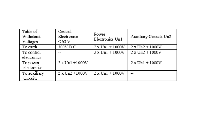
D.C. test voltages may be applied instead of A.C. The magnitude of D.C. test voltages to be applied shall be √2 times the above mentioned A.C. (r.m.s.) values.
Load-Duration Test
All converters to be supplied as part of the purchase order shall be subjected to a load duration test performed at rate voltage for a period of not less than 48 hours prior to the execution of functional tests.
At least one converter shall be loaded to its rated output, at 0.8 power factor lagging, throughout the 48-hour test period.
If an appropriate load is not available to conduct the test, then it shall be carried out using a resistive load.
The load resistance shall then be such that the inverter D.C. input current is the rated value.
All other converter to be supplied as part of the purchase order may be energized under partial load or zero load current conditions throughout the test period.
Manufacturers test reports shall state the dates and times on which the load duration test was performed and shall record details of load currents and any circuit or component malfunction identified during the test period.
Functional Tests
Functional tests shall be performed on all converters.
If, during the execution of functional tests, an electronic component of the converter is required to be replaced, e.g. due to converter malfunction or failure of the unit to fulfill the performance requirements of the specification, then the converter load-duration test shall be repeated at rated current following which the functional tests shall be carried out.
The manufacturers standard test protocol will be acceptable provided it is no less stringent than that specified below.
Tests and measurements marked (**) may be omitted subject to the manufacturer submitting tender, details of the availability of test records (including dates and location of tests) which verify the specified performance values.
Rectifier Load Test at Constant Output Voltage
Measurements shall be carried out in the rectifier float-charge operating mode.
In each mode, measurements shall be carried out at nominal A.C. supply voltage and at zero, 50% and 100% of rectifier full load direct current.
Measurements at 100% full load current shall be repeated at 90% and 110% of nominal A.C. supply voltage.
Measurements shall comprise of:
- Input phase voltage and frequency
- Input phase current
- Input power
- D.C. output voltage
- D.C. output current
Rectifier load test at constant output current limit.
Measurements shall be carried out in the rectifier float-charge operating mode.
Measurements shall be carried out when the rectifier is operating under D.C. output current-limiting conditions with the D.C. output voltage between zero and the set value corresponding to constant voltage operation.
Measurements shall comprise of:
- D.C. output voltage
- D.C. output current
Inverter static load tests
Measurements shall be carried out at zero, 50% and 100% of inverter rated output current with the load being a balanced 3 phase load and shall be repeated for inverter D.C. input voltages corresponding to battery float-charge operation and the rated maximum and minimum inverter input voltage.
Measurements shall comprise of:
Input voltage
Input current
Output voltage, frequency and waveform distortion
Output phase current(s)
Output power
Balanced Load Test:
The static load test described above for 1-phase inverters shall be carried out on 3phase inverter, the load being a balanced 3-phase load.
Unbalanced Load Test:
Measurement shall be carried out under unbalanced load conditions such that the current in one phase of the inverter differs from that in the other two phases by 50% of the rated output current.
Measurements shall be carried out for inverter D.C. input voltages corresponding to battery float-charge operation and the rated maximum and minimum inverter input voltage.
Measurements shall comprise of:
- Input voltage
- Input current
- Output voltages
- Angular displacement of output phase voltages
- Output currents
Inverter dynamic load tests
Measurements of inverter output voltage variations shall be recorded in response to:
Instantaneous load changes of 100% rated output.
Measurements shall be recorded when the load is switched to/from the inverter via the static bypass switch and via the load circuit switch.
Application of a short circuit to the inverter output via a slow-acting (type g1) fuse link having a current rating nearest to 10% of the UPS unit rated output, the bypass circuit being isolated.
Static Bypass Switch Tests
Measurements shall be carried out to verify the correct functioning of the bypass circuit voltage and frequency monitors, and the inverter/bypass synchronous operating controls.
Measurements of the load voltage waveform(s) shall be carried out during the following load transfer tests which shall be performed with the UPS unit delivering any load between zero and its rated output, and with the inverter operating in synchronism with the bypass circuit supply:
Load transfer bypass initiated by manual operation of load transfer switch.
Load transfer to bypass initiated by simulating inverter malfunction.
Load transfer to bypass initiated by short circuiting of fuse protected load circuit (**).
Load retransfer to inverter initiated automatically and manually.
Lock-out of automatic load retransfer on sustained and recurring fault.
Load transfer and retransfer from one inverter to the second inverter.
Auxiliary Equipment and Control Circuit Tests
The correct functioning of all measuring instruments, alarms and indications, protection and controls specified, shall be verified.
Battery Discharge Test
A battery discharge test shall be performed at a current corresponding to the inverter input current when the inverter is delivering its rated output kVA at 0.8 power factor lagging.
The following measurements shall be recorded:
Battery voltage after the specified discharge time.
Battery discharge duration at the instant of inverter shutdown initiated by the D.C. circuit low-voltage monitor.
Discover more from Method Statement Store
Subscribe to get the latest posts sent to your email.