The purpose of this method statement is to define the sequence and working methodology of the positioning, installation, testing, commissioning and startup of DC system & Battery bank at a project.
Prior to commencement of work, all shop drawings will be processed and submitted for approval by consultant/client.
Shop drawings will show the layout of 48V DC systems as well as the section drawings.
Only approved shop drawing will be used for installation.
Subcontractor shall organize time and date with all relevant parties to witness battery installation testing and commissioning activities.
Also contractor shall organize for the monitoring and documentation of test results.
After the battery has been tested and commissioned and all the relevant paper work completed, it shall be handed over to the Client/Main Contractor.
Below is list of necessary tools and equipment for the installation and testing of battery charger and battery bank.
- Electrician hand tools
- Lifting equipment’s (Manual Geni lift & Electrical scissor lift)
- Lift hoist (electrical, for vertical riser)
- Calibrated megger, Torque wrench & Multimeter
- Calibrated laser light
- Spirit level
- Plum (with thread)
- Scaffolding
- Trolley
All instrumentation used for the testing of the batteries must have up to date calibration certificates.
The following test instrumentation & tools will be required to undertake the tests detailed within this procedure:
Digital Multimeter (AC/DC) True RMS for Voltage measurements
Clamp on Ammeter (AC/DC) for Current measurements
Torque wrench (10 NM – 100 NM)
Thermometer
Hydrometer (1.1-1.3)
HSE Requirements
Refer to approved risk assessment and any special conditions as per the Permit to Work.
Ensure all members of Staff who have signed the above document read and understand the risk assessment and the special conditions for the Permit to Work.
A tool box talk will occur prior to any work to ensure all parties involved are aware of any special conditions appertaining to the described work.
Roles and Responsibilities:
Project manager shall be responsible overall to complete all MEP works as per specifications, budget, time, & quality.
MEP Site Engineers shall be responsible for but not limited to the following important activities:
To ensure that all the preparation and application works are carried out according to the contract specification and manufacturer’s data sheet(s).
Ensure that the progressing of works is carried out according to the planned program, and as per the approved Method statement.
To ensure that all the equipment’s and materials required in executing the works are available according to the planned construction program.
Coordinate with the main contractor’s MEP coordinator and safety officer for all safe and proper execution of the work in accordance with the risk assessment.
To coordinate with the civil team for any area preparation, access, clearance.
Site Foreman shall be responsible for but not limited to the following important activities:
To guide and control the tradesmen and charge-hands(s).
Ensure that work is done as per the approved shop drawing(s).
To report to the MEP site engineer.
Health and Safety Officer shall be responsible for but not limited to the following important activities:
Ensure health and safety of the site personnel.
Ensuring that all PPE available with site personnel.
Good housekeeping on site
Environmental concerns are addressed.
Responsible for implementation and assurance of the safety and environmental requirements (JSEA).
Quality control engineers shall be responsible for but not limited to the following important activities:
Inspecting the materials on site as per approved materials submittal and raise MIR within 24 hrs prior to installation on site.
Inspection for the installation as per approved drawings and approved test plans and checklists.
Preparing test forms for testing on site and updating results accomplished.
Issuing inspection request within 24 hours before the actual inspection.
Responsible for the assurance of Quality control, method statement and inspection test plan.
Controlling the shop drawings flow on site.
Storage and Handling of Equipment’s
The critical source panels, i.e. chargers, inverters and distribution boards are built up of single cabinets in fixed technique.
Basic elements of the frames are C sections of 2mm thick sheet steel with holes at 25mm intervals.
The parts of the frame are secured with thread forming screws and require no maintenance.
Single cabinets are separated by separation walls.
The cabinets are equipped with rear plates, hinged front doors and end plates.
Intermediate Storage : The nature and duration of intermediate storage are dependent on the type of packaging.
Cubicles in standard packaging:
Store indoors after arrival where no condensation can occur.
Unpack immediately.
Open the doors for several hours to acclimatize the equipment.
Cover the cubicles with plastic sheeting for any subsequent storage periods.
Check regularly for condensation forming under the sheeting until the start of installation.
Cubicles with export/ seaworthy packaging:
Moisture protection is only guaranteed if the packaging is undamaged.
Possibility of intermediate storage outdoors.
Storage period of maximum 12 months if wrapped in heat sealed PE sheeting and the packaging is undamaged.
When the storage period is exceeded , the drying agent must be replaced and the plastic sheeting has to be resealed.
Cation: If condensation occurred don’t commission the unit until it is completely dry.
Open the doors for several hours to acclimatize the unit or run the cubicle heaters for 2-3 days.
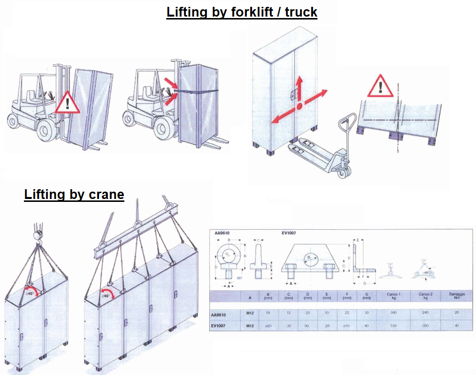
Transporting the Cubicles/Units
The unpacked cabinets can be transported by crane or fork-lift snuck.
Cubicles have to be transported only in the vertical position.
Tilting and canting must be avoided.
Cubicles may easily tip over when transported with a hand-pulled truck. Therefore the distance between the wooden cross beam or the pallet and the underground should not be more than 3 mm.
Checks on delivery
Check the consignment on arrival at site for completeness and any transport damage (if found, determine extent, cause and originator).
When damage is detected it must be proceeded as follows:
- Immediately write down visible damage in the consignment note.
- Report hidden damage in writing to the relevant forwarding agent within one week.
- When certification is missing or a claim has not been made, the manufacturer can disclaim all liability.
Constructional requirements
To prevent damage being caused by moisture and dirt the following tasks (only examples) must be carried out before erection of the panels:
Walls and ceilings DRY, painting completed.
Doors and windows installed.
Openings in the floor, wall and ceiling for cables conductors pipes bars and ventilation in accordance with the construction drawings provided.
Supporting brackets, beams, enclosures and foundation frames assembled and painted.
If necessary, assemble braces appropriate to the basic dimensions of the switchgear installation with cross struts corresponding to the cubicle divisions.
Suitable indoor conditions must be maintained.
Adequate lighting as well as free access to the cubicle rooms must be provided.
Excessive temperature fluctuations together with high humidity should be prevented by heating the room.
Condensation should also be prevented.
Erection and connection of the cubicles
The erection of the cubicles should be carried out, as described the following: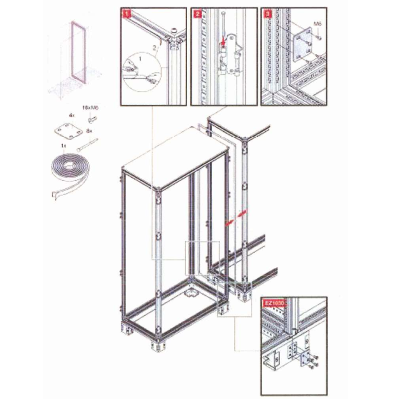
The shipping units which are to be erected in one row have to be aligned accurately and checked that they are vertical.
Doors and panels must not be twisted or stressed.
The erection can start at the left or at the right.
Note: for protection class IP5x and higher or IPx1 and higher the rubber seal has to be be attached between the frames.
The frames of the shipping units have to be screwed together.
The vertical sections are already fitted on the front and rear with special nuts.
Additionally to the vertical sections or if the access to the joints in the vertical sections is obstructed, the bottom sections can be screwed together using the frame connectors which are enclosed.
The protective conductor (PE or PEN) is to be connected to the PE/PEN bar.
Additional connections to the central earthing system can be made at any point of the perforated PE/PEN bar. Local regulations must be complied with.
The lifting angles may be removed and afterwards the fastening holes have to be plugged with attached plug.
Additional information for switchgear positioning
The area around the cubicles to be left clear should be at least 80 mm.
To be able to mount the last (right) cubicle, the distance between the end cubicle and the (right) wall must be at least 150 mm.
In case of left-mounted doors, the minimal distance between the (left) wall and the (left) end cubicle should be also 150 mm, such that the door can be opened in an angle of more than 90°.
The distance from the upper edge of the (highest) cubicle to the ceiling should be at least 500 mm for cubicles with ventilation grids on the top.
Fastening methods to foundation
The erection of switchgears having the cable entries at the bottom requires a foundation with an opening, a cable duct or a special base frame.
The cubicles should preferably be erected on a base frame which is either embedded in the concrete floor or rests as false floor on supports.
When erecting the base frame the following must be observed:
- The base frame should be aligned and checked under the supervision of a suppliers
- The horizontal tolerance of the frame must not exceed +1 mm over a length of 1 m. This is to be ensured by using suitable levelling devices (e.g. spirit level, 1 m long surveyors rod)
Frame must not ondulate (2/1000 according to DIN ISO 1101).
The levelling of base frames can be performed e.g. with PRESTOJACK levelling spindles.
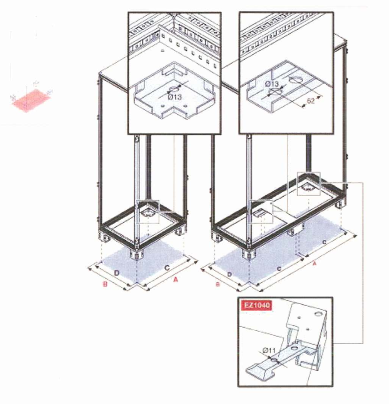
During erection the switchgear is welded or screwed to the base frame.
The length of the weld seams at the front and rear of each cubicle should not be less than 20 mm.
All welding’s must be protected against corrosion by a coat of paint (e. zinc paint).
The screwed connection is carried out through the transverse section.
Mounting holes required for metal straddling dowels M 10 must be drilled during erection.
When false floors are used, notice that:
Tolerances are the same as for the base frame.
The subsoil must be firm, so that the tolerances are not exceeded by settling of the soil (especially when using insulation layers and adhesives).
The false floor has to have a carrying capacity of p=20 kN/m2 (Compression load from top to bottom).
During erection the switchgear is welded or screwed to the false floor.
The length of the weld seams at the front and rear of each cubicle should not be less than 20 mm. Then a reliable earth connection is provided. All welding’s must be protected against corrosion by a coat of paint (e.g. zinc paint).
If welding is not possible, the switchgear can be bolted to the false floor. The necessary mounting holes should be drilled on site.
Care should be taken to ensure that the base sections of each cubicle rests evenly on the supports.
Taking into account the bending radius of the cables and adequate accessibility, a minimum floor height of 500 mm is recommended.
Drip protection roof (optional)
A drip proof top is only recommended if tubes containing water or other solvents are placed above the cubicles.
The top shall be installed only after the cubicles are placed and screwed together.
Mount the lifting bolts (or tubes) and install the tops.
CABLE CONNECTIONS & WIRING
Power and control cables are to be attached to the cable mounting rails in the cable compartment.
Power and control cables are to be stripped off their jacket below the connections of each module.
Before fastening the cables at the power terminals they must be supported or bended so that no tension or pressure is exerted on the cable connection unit.
Control cables with individual conductors to be connected to several different terminal blocks are to be stripped within the cable compartment.
Prior to fastening any feeder-, load- or control cable the protective conductor (PE or PEN) must be connected to the cabinet ground bar.
The continuous connection of the protective conductor circuits to inactive metal parts of the building (in accordance with IEC 60439 or DIN VDE 0100 Part 540) is to be carried out according to the conditions at the erection site.
The terminal list is part of the Set of Drawings for each cabinet.
Battery charger Testing and Commissioning Method Statement
The following test procedure has been prepared as a guideline for testing of Battery chargers.
Procedure will be adopted for testing and commissioning of all Battery chargers on the Project.
All Testing & Commissioning of Battery chargers will be carried out by specialist supplier under the supervision of MEP contractor or as per prior agreement.
Pre-commissioning requirements
Carry out the following for each Battery charger prior to starting any testing.
General Checks
All packing material removed from unit and that air inlets and discharges are free from obstruction.
There is no visual damage to the external casing of the unit or damage to the internal parts.
All transit bolts, wedges etc. have been removed from panels and that they are free to move.
Room is in a condition fit for commissioning to commence. Room cleaned and free of dust, secure with doors installed.
Documentation Checks
All the approved drawings SLD, GA and Schematic are available for verification
Applicable/relevant specification is available for verification
Approved equipment layout is available for verification
Battery charger panels are installed as per approved equipment layout
Site acceptance test formats are approved
The test equipment to be used, possess valid calibration certification
Installation Checks
Confirm battery charger panels are installed as per approved equipment layout
Check and confirm that all electrical terminations are securely tightened.
Confirm the electrical connections are correct and that the unit is isolated.
Record nameplate information and compare with specification provided. Highlight any discrepancy noted.
Check power supply is present at the unit at the correct voltage.
Verify circuit has been tested and approved by the electrical contractor.
Commissioning / Test Procedures
Perform the following Commissioning / Performance Test for each battery charger
Equipment verification
The battery charger under test shall be verified for proper Configuration / Scheme, voltage ratings, Current ratings, Outgoing feeder quantity, Outgoing feeder ratings…Etc.
The observations, Test results and Deviations from requirements shall be recorded in prescribed SAT (Site acceptance test) format.
Parameter verification
The parameter settings set in battery charger to be verified to meet the requirements referred in the specification and to meet the battery requirements referred by the OEM (Original equipment manufacturer).
Observations, Test results and Deviations from requirements shall be recorded in prescribed SAT (Site acceptance test) format.
VCU (Voltage Control Unit) Test:
Rectifier output voltage is manually increased from 43V to 70.4V, to manage output voltage depends upon rectifier voltage, and Diodes will pick & drop, in each step note down all the Stage-1, stage-2 & stage-3 voltages.
Same will be continuing till 70.4V.
Same procedure has to follow by decreasing the voltage from 70.4V to 43V.
The observations, Test results and Deviations from requirements shall be recorded in prescribed SAT (Site acceptance test) format.
Special exceptions: In some cases it may be possible to have Distribution feeder voltage out of limits at NO LOAD. A minimum of 20% of rated Distribution current shall be applied while performing this test.
Capacity Test
Capacity of the battery charger under test shall be verified by applying dummy load external to the battery charger panels.
The battery charger shall supply the rated continuous output current without any damage to itself and without generating any warning/ Alarm.
The observations, Test results and Deviations from requirements shall be recorded in prescribed SAT (Site acceptance test) format.
Special exceptions: In some cases it may be possible to have OVER LOAD ALARM generated due to error in measured values though the equipment is calibrated, in such case the calibration may have to be carried out if necessary.
Over load and Total current limit Test
Over load sustainability of the battery charger under test shall be verified by applying dummy load more than rated capacity external to the battery charger panels.
The battery charger shall supply the rated continuous output current without any damage to itself and shall generate over load Alarm.
If the externally applied dummy load is more than the pre-set level, the battery charger shall reduce the output voltage to maintain total power constant.
The observations, Test results and Deviations from requirements shall be recorded in prescribed SAT (Site acceptance test) format.
Special exceptions: In some cases it may be possible to have Distribution feeder voltage out of limits at OVER LOAD. In such case, reducing the applied load shall normalize the situation
Battery current limit Test
The battery charger shall limit the current being fed to battery as per OEM recommendations.
Battery current limit function of the battery charger under test shall be verified by applying dummy load in battery path more than the preset level.
The battery charger shall supply the pre-set battery current level with reduced voltage.
Further increase in applied battery path current by dummy load shall further reduce the output voltage maintaining same battery current.
The observations, Test results and Deviations from requirements shall be recorded in prescribed SAT (Site acceptance test) format.
Special exceptions: In some cases it may be possible to have Distribution feeder voltage out of limits during battery current limit. In such case, reducing the applied load shall normalize the situation.
Alarm Test
The battery charger shall generate alarms for prescribed events/ incidents like fuse fail, voltage out of limit s, feeder trip etc.
All the alarms shall be verified to meet the specified requirements which include local indications and potential free contacts.
The observations, Test results and Deviations from requirements shall be recorded in prescribed SAT (Site acceptance test) format.
Battery Testing and Commissioning Method Statement
Carry out the following for each Battery prior to starting any testing.
General Checks
Confirm all packing material removed from batteries.
Confirm there is no visual damage to the external casing of the unit or damage to the internal parts.
Confirm room is in a condition fit for commissioning to commence. Room cleaned and free of dust, secure with doors installed.
Confirm ventilation arrangement in battery room as per battery manufacturer recommendations.
Documentation Checks
All the approved drawings SLD, GA and Wiring are available for verification.
Confirm applicable specification is available for verification.
Approved equipment layout is available for verification.
Confirm the Site acceptance test formats are approved.
All the test equipment to be used, possess valid calibration certification.
Installation Checks
Confirm Batteries are installed as per approved equipment layout
All electrical terminations are securely tightened.
Confirm the electrical connections are correct and that the unit is isolated.
Record nameplate information and compare with specification provided. Highlight any discrepancy noted.
Check power supply is present at the unit at the correct voltage.
Verify circuit has been tested and approved by the electrical contractor.
Commissioning/ Test Procedures
Perform the following Commissioning/ Performance Test for each Battery
Equipment verification
The Battery under test shall be verified for proper Configuration/ Scheme, Voltage ratings, Current ratings…Etc.
The observations, Test results and Deviations from requirements shall be recorded in prescribed SAT (Site acceptance test) format.
Electrolyte filling checks
The Battery shall be filled with the electrolyte supplied along with the batteries. The electrolyte level shall not be more than 20mm above the low level mark.
After filling allow the battery to soak for a minimum of 4 hours to maximum 24 hours.
The observations, Test results and Deviations from requirements shall be recorded in prescribed SAT (Site acceptance test) format
Battery Charging Procedure/Checks
Adjust the electrolyte level if necessary.
Open circuit values viz voltages, shall be recorded in prescribed format.
The Battery shall be charged for 30 hours at l.65V per cell and at 0.2 C5 A current.
During charging, the battery shall be monitored and the readings shall be recorded on hourly basis.
After completion of 30 hours charging, the batteries can be kept on Floating if not possible to carry out the capacity test.
The observations, Test results and Deviations from requirements shall be recorded in prescribed SAT (Site acceptance test) format.
Battery Capacity Test
Adjust the electrolyte level if necessary.
Open circuit values viz voltages, shall be recorded in prescribed format.
The Battery shall be discharged for 5 hours at 0.2 C5 A current to an end cell voltage of 1.00 V per cell.
During discharging, the battery shall be monitored and the readings shall be recorded on hourly basis.
After completion of 5 hours discharging, the batteries shall be kept on recharging.
Any individual cell voltage shall not fall below 1.0 V if discharged at 0.2C5 A.
The observations, test results and deviations from requirements shall be recorded in prescribed SAT (Site acceptance test) format.
Special exceptions: In some cases it may be required to consider end cell voltage 1.05V per cell. In such a case, the discharge current shall be as per battery manufacturer data sheet.
Re-Charging checks
Adjust the electrolyte level if necessary.
Open circuit values viz voltages shall be recorded in prescribed format.
The Battery shall be recharged for 30 hours at 1.65C per cell and at 0.2 C5 A current.
During re charging, the battery shall be monitored and the readings shall be recorded on hourly basis.
After completion of 30 hours re-charging, the batteries shall be kept on Floating.
The observations, Test results and Deviations from requirements shall be recorded in prescribed SAT (Site acceptance test) format.
Cell oil filling checks
The Battery shall be filled with cell oil as per Battery manufacturer data sheet before putting it in service.
The observations, Test results and Deviations from requirements shall be recorded in prescribed SAT (Site acceptance test) format.
Discover more from Method Statement Store
Subscribe to get the latest posts sent to your email.