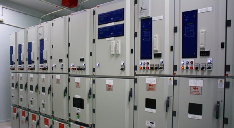
This method statement covers the electrical installation of LV switchgear and load center. Installation shall be in compliance with project electrical specifications, manufacturer instructions, applicable codes and international standards.
Packaging, identification, delivery and storage shall be as per supplier recommendations and approved handling and storage procedures.
Other reference documents include:
- Project Quality Plan
- Project HSE Plan
- Approved Layout and Detail drawings
Overall project manager and electrical installation engineer are responsible for the implementation of this electrical method statement including all relevant quality and HSE requirements.
Necessary Tools & Equipment
Following tools shall be arranged before starting the job.
- Special Tools (if any) needed for the installation or assembly of switchboard or load center – refer to supplier instructions.
- Forklift, Boom Truck/Boom Loader
- Portable Hand Tools.
- Portable Drilling Machine.
- Grinding Machine.
- Insulation Testing Equipment.
- Digital Multimeter.
- Measuring Tape.
- Ladder/ Scaffolding.
- PPE such as safety shoes, safety helmet, safety glasses, fluorescent vest, safety gloves and dust mask as required.
Prerequisites for Panel Installation
Permit to work PTW shall be obtained before starting the switchgear installation work.
Make sure the installation of necessary barricades and safety signages.
Ensure that the work area / electrical room is ready, released from civil contractor and safe to start the installation of LV Switchgears and Load Centers.
Arrange adequate lightings and ventilations as required.
Ensure that the issued materials are according to the approved specifications / submittals and as per the requirement of the area shop drawings. (i.e. Make, Size, Model, Type & Capacity etc.)
LV Switchgear and Load Center Installation Procedure
Installation works shall be carried out only with respect to approved shop drawings of latest revision.
All components of LV Switchgears and Load Center Shall be verified against the approved material submittals.
Transportation from warehouse to the installation area shall be in vertical position only, lifting shall be done using supplier provided lifting eye/brackets only.
Unpacking will be done at the time and place of installation, final verification of the switchgear, load center and accessories shall be done as per the equipment schedule and detail drawings etc.
Erection steps and Positioning
Refer the IFC drawing/shop drawing for fixing details including the base frame installation.
Ensure the floor surface is ready with base frames grouted for the switchgear panel installation.
Minimum clearance of 750 mm shall be maintained at rear side of the panel for easy access and termination of cables and other maintenance works.
Panel boards shall be installed serially with proper level & verticality in accordance with the Manufacturer’s recommendations, approved site layout and as per site requirements under the supervision of supplier/manufacturer representative.
Complete all cabinet interconnections, bus bar connections, control wire connections between the cubicles after proper alignment of the sections, as per manufacturer’s drawing and approved shop drawing.
Mechanical connection or joining of the compartment shall be done as per supplier installation procedure.
All knockouts made on the panel covers shall be filed and provided with grommets to avoid sharp edges and unused knockouts shall be covered.
The connection of bus bar trunking with all panel boards shall be done rigidly with proper supports.
Bus bar connection shall be done with proper tools to achieve required torque.
Cables bending radius should be less than the 8 times of the cable diameter in line with the cable manufacturer’s recommendation.
Cable pulling, termination & crimping shall be done as per cables installation method statement.
Termination of cables shall be done using approved material submittal for cable glands and lugs.
Cable glanding and connections shall be done only by competent technicians / electricians under supervision of electrical site engineers.
Pre-stressing/Fixing shall be done using the torque wrench for all connections.
Grounding / earthing of the switchgear or load center shall be done properly as per grounding diagram, and approved shop drawings.
Manufacturer recommendations are to be followed for all relay, timer and other breaker current settings, as per the total connected loads and the discrimination study of the system.
Identification labels of approved type shall be fixed on all panel boards.
Coordinate with the main contractor and ensure provision of checkered plates on the open trenches inside the LV Room and Electrical rooms.
Ensure that all cable entries and other openings of Electrical / LV Room, Wall / Floor are sealed by using the approved sealant.
The manufacturer’s representative to verify the site installations and provide acceptance of same prior to Energization of Panel boards after obtaining clearance from Site Engineer.
Raise (WIR) for installation of Panel Boards along with glanding and termination to client for approval.
Electrical connection and wiring shall be done properly and offered for inspection and approval from client.
Discover more from Method Statement Store
Subscribe to get the latest posts sent to your email.