This method statement covers the Installation of Public Address System at any kind of building construction or renovation project.
The public address system shall provide to public areas background music programs, live message and recorded or synthesized voice messages.
PA system shall be fully programmable and shall be controlled and monitored on digital bases by the central and sub-control modules.
Equipment installation shall comply with specifications, approved drawings and manufacturer’s recommendations.
The PAS supplier shall be responsible to coordinate and exchange information with other contractors in order to achieve the required integrated functions.
Other necessary coordination includes but not limited to methods of communications, interface with software, protocols and fire alarm system etc.
Project / construction manager shall be responsible for the overall implementation of this method statement, and to ensure that section engineer and general foremen are well informed of public address system installation requirements.
PA system installation work shall be carried out by the site staff under strict supervision and guidance of the concerned Supervisors / Foremen / Engineers.
On receipts of the material at site, necessary precautions shall be taken for unloading, shifting and storage of material inside the warehouse.
Necessary Tools & Equipment
Following tools shall be arranged before starting the installation job.
- General Electrical Toolbox
- Digital Multimeter
- Boom Loader / Crane
- Nylon slings
- Measuring Tape
- Ladder / Scaffoldings
- Portable Hand tools.
- Crimping Tools, Plier, Cutter.
- Torque Drivers and Wrenches
- Safety requirement tools such as safety shoes, safety helmet, safety glasses, fluorescent vest, safety gloves and dust mask as required.
Prerequisites for Public Address System Installation
Before commencing the installation of public address systems following checks will be carried out:
- Check access is available to the area where pa system installation shall be done.
- Latest approved shop drawings are available.
- Ensure other site activities around the installation location are finished and no other construction activity is pending by other disciplines.
- Ensure all GI trunking, GI conduits, cable pulling work and power sockets are completed as per approved shop drawings and cable continuity testing is done and approved by client/consultant.
- The work area is clean and safe and the competent electricians have valid permit to start work.
- Adequate lightings are provided as required depending upon site conditions.
Installation of Public Address System
Central equipment including the central controller, amplifiers, music sources, server etc. shall be installed in purpose made 19” racks in the BMS control room of the building.
The rack shall have a lockable front glass safety door and adequate ventilation louvers including ventilation fan.
Rack cabinets shall also have storage spaces for cables and accessories.
Central equipment shall be grounded as per approved wiring diagram.
After installing the central equipment preliminary approval to be taken.
Installation of Loudspeakers – Ceiling Mount Speakers
Before installation or use, be sure to carefully read all the instructions recommended by the speaker manufacturer.
The location of ceiling mount speaker must be as per approved reflected ceiling layout/plan.
Install the unit only in a location that can structurally support the weight of the unit and the mounting bracket, doing otherwise may result in the unit falling down and causing personal injury and/or property damage.
Using the supplied paper pattern as a guide, open a mounting hole of the dimension as per manufacturer instructions.
Hook the speaker mounting spring into the mounting hole in the ceiling.
Make wiring; insert the lead-in cables (cables from the amplifier) and lead out cables (cables to other speakers) into the input connector.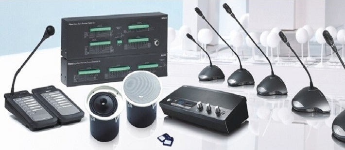
Change the input impedance as needed.
When changing the input Impedance, detach the black wire connected to the matching transformer, and reinsert it into the desired input tap as per manufacturer instruction.
Never connect to the 330Ω tap in a 100V line system, as excessive input power is applied to the speaker, possibly resulting in damage.
Push the panel surface into the mounting hole.
Recheck the speaker installation after completion of work and raise installation inspection request.
Suspension Speakers Installation
Before installation or use, be sure to carefully read all the instructions recommended by the manufacturer.
Install the speakers on a recommended structure that can support the weight of the unit and the mounting bracket.
Secure the ceiling bracket to the ceiling with the help of 4 screws. Pull both the lead-in and lead-out cables through the cable hole in the bracket.
Pass the speaker cord through the supplied ceiling cover, and cut the cord to the desired length.
Run the speaker’s cable through the cable holes in the mounting hanger, and then connect it to the input connector.
Put the mounting hanger onto the ceiling bracket’s hook.
Connect both the lead-in and lead-out cables to the input connector.
Push the ceiling cover, slipped over the cord onto the ceiling surface, and then tighten the cover-retaining nut using a 17mm (0.67”) hex wrench.
In the case of exposed wiring, notch the cable entry tab on the rim of the cover, then make connections.
Components and Cables Labeling
Identification of devices shall be done according to manufacturer’s written instructions, equipment schedule and compliance with specifications.
Color code conductors and apply wire and cable marking tape to designated wires and cables to identify media in coordination with system wiring diagrams.
Installation of labels to be completed where indicated and at locations for best convenience of viewing without interference with operation and maintenance of equipment.
Labels for all cables will be attached according to the project electrical specifications.
PA System Testing and Commissioning Procedure
Carry out a visual inspection of outside & inside of installed speakers and control room equipment.
Visually check to ensure that all equipment is installed in line with Approved Construction drawings, Approved Material Submittal, Project Specification and in line with manufacturer’s recommendations & security standards.
Record results on commissioning report.
Pre Commissioning Checks and Cold Testing
Following checks will be made prior to powering up the system by the specialist suppliers/manufacturer representative.
The PA system speaker, Data and power cabling has to be mandatory Checked & rectified of all Open/Short/Earth Faults prior to commencement of connection & powering up of the Speakers and control equipment.
Disconnect Speakers and Control room equipment and test open circuit, short circuit and earth fault with calibrated multimeter.
This has to be done by contractor and necessary Continuity Reports have to be filled in, these reports then becomes part of the Testing & Commissioning dossier.
Address each speaker as in layout drawings.
Record results on electrical test sheets and commissioning report.
Power up Tests and Commissioning
Check Mains (P, E, N, L) cables
Check data cable polarity.
Check Mains Voltage.
Check Coaxial cable termination.
Energize the incoming Mains Supply to Amplifier and control equipment.
Power up equipment one by one.
Wait for the system initialization.
Start function test of equipment.
Record if any speakers are not reporting.
Record all the equipment functionality performance.
Ensure all connected speakers and control room equipment are reporting back the full status and are fault free.
After successful commissioning the results will be recorded on the testing and commissioning sheets which are given as attachment with ITP document.
Discover more from Method Statement Store
Subscribe to get the latest posts sent to your email.