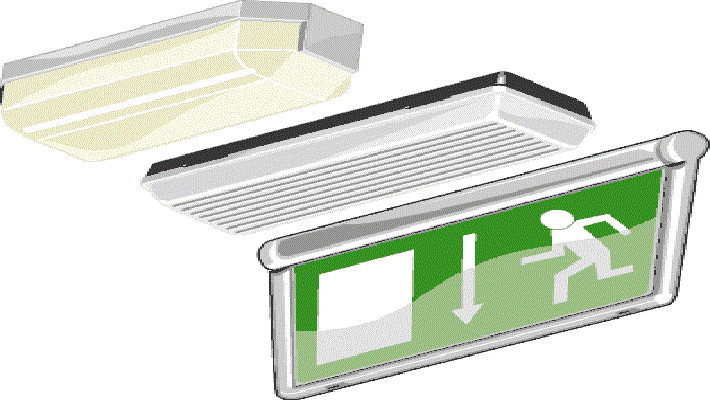
The below electrical installation method statement describes standard operating steps to install the emergency lighting system or central battery system.
This method is applicable for any kind of project, you can modify the method statement as per different project requirements.
We have given this as a general guide and manufacturer instruction and site specific specification should be followed while doing the installation of central battery emergency lighting.
Necessary Tools/Equipment
Below is list of tools and instruments generally required for installation of emergency lighting.
- Drill machine
- Portable electric drill
- Forklift
- Step Ladder
- Scaffolding Platform
- Digital Multifunction tester
- Spirit Level, Water tube & Plumb
- Hammer
- Hacksaw
- Marker and Masking tape
Installation Steps for Emergency Lighting System
Exposed conduits shall be GI and parallel with or at right angles to building line, beams, or ceiling.
For all change in direction symmetrical bends or metal boxes to be used.
Approved emergency lighting cabling i.e. FP 200 will be used only.
Provide suitable sleeves wherever the emergency lighting cable passes through walls, floors, floor screeds, bricks walls etc.
Carryout the insulation resistance test before terminating the cables.
Uniform color coding shall be used throughout the installation.
Connections to the terminals shall be tightened to avoid any loose connections, and earth connection points should be clean in order to provide good electrical conductivity path.
Ensure the installation of luminaries as per approved shop drawings.
Exit lights shall be installed as per approved drawings on all escape routes and their orientation should be perfect i.e. should be visible from all sides and exit direction to be proper.
Install all safety luminaries to cover the specific hazards and to locate the safety equipment installed.
Intersections with other corridors, level changes, staircases, fire alarm call points and operation equipment and other life safety equipment will be done as shown in the approved shop drawings.
All emergency lights having high frequency ballasts will have a built in or separate monitoring facility as approved already and monitoring module to be installed and addressed before fixing the luminaries.
All panels & equipment shall be connected and labelled as per approved shop drawing & schematic diagrams.
Make sure that all cabling and connection are completed with BMS as applicable.
Circuit details to be provided in the panel board.
Make sure that all metallic equipment, accessories & light fittings are properly earthed.
All equipment to be fully leveled, aligned and tightened properly.
After completion of work equipment sections and compartments should be cleaned to remove any dust and other debris etc.
The following tests to be done either by approved engineer or by supplier as applicable on the site specific requirements i.e. polarity check, incoming power supply phase sequence check, fixing battery fuse box, cabling of battery and panels.
Discover more from Method Statement Store
Subscribe to get the latest posts sent to your email.