This method statement covers the installation of floor mounted Close Control Units CCU with down flow air delivery serving the room.
Following this procedure will ensure the CCU installation has been carried out as per project/contract specifications and manufacturer’s recommendations.
The mechanical method statement gives details of how the work will be carried out and how health and safety issues and controls shall be implemented.
CCU shall be installed in different locations as per the project requirements i.e. server rooms, telecom rooms and equipment room as shown in the project approved drawings.
Plant and Equipment
Below is list of necessary tools and equipment for the installation of close control units.
- Mobile Crane or other suitable lifting equipment
- Spirit Level
- Electric Drill
- Measuring Tape
- Hand Hammer and Punching Tool
- Adjustable Wrench
- Mobile Hoist or other suitable equipment
Personnel Roles and Responsibilities
Package/Project Manager will be overall responsible for complete MEP works.
MEP Site Engineer will be responsible for:
Preparation and application works are carried out according to the contract specifications and manufacturer’s data sheet(s).
The progression of works is carried out according to the planned program, and as per the approved method statement.
All the equipment and material required in executing the work are available according to the planned construction program.
The coordination with the main contractor’s MEP coordinator and safety officer for all safe and proper execution of the works in accordance with the risk assessment.
Coordination with the Civil Engineer.
MEP Foremen will be responsible for:
Guidance and control of the tradesmen and charge-hands.
Ensuring the work is done as per the approved shop drawings.
Reporting the work progress to the MEP Site Engineer.
Safety Engineer will be responsible for implementation and assurance of safety and environmental requirements as per the approved risk assessment or job safety analysis JSEA.
Quality Control Engineer will be responsible for the implementation of the work method statements, ITP and checklists.
Receipt Handling and Storage of CCU Equipment
Upon receipt of the equipment, a visual inspection must be done and any damage must be noted on the delivery note. Particulars of any damage or short delivery must be endorsed by the driver delivering the equipment. All claims for damage, or incomplete delivery, must be notified to the manufacturer / suppliers.
Off-Loading
The closed control unit will be supplied on pallets unless otherwise specified, and will be offloaded from the delivery vehicle using a forklift or similar equipment.
Under no circumstances the units be handled in such a way as to cause damage to the peripheral connections and other fittings etc.
Storage
Should it be necessary to store units on site for any period of time prior to installation, they must be stored in a clean, dry, secure area, where any possibility of damage to the units is eliminated.
It is essential that suitable instructions are adhered to and implemented during the period of storage prior to installation, testing and commissioning.
For long term storage of closed control units refer to the user manual and comply the requirements.
CCU Installation Steps
Make sure the CCU installation in accordance with the the manufacturer instructions and as per approved shop drawings.
When raising the CCU into position, secure it to a sufficiently strong overhead structure with straps, slings and or belts for safety to prevent it from falling.
Spreader bars may be required with some lifting or securing methods to prevent damaging the unit.
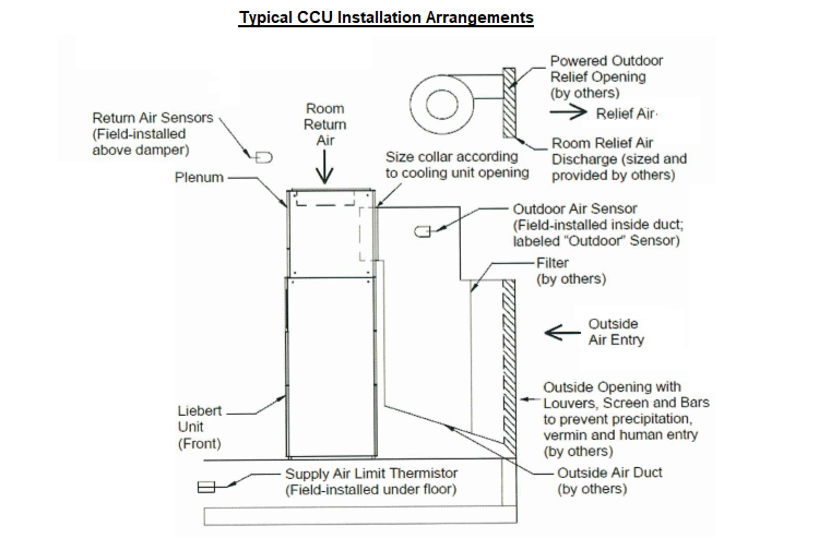
The ductwork to the outside must be constructed to configure with the outside air intake on the rear of the CCU.
For duct dimensions and specifications, refer to the approved shop drawings and manufacturer’s instructions.
Diagram below is a typical indicator of the installation of the CCU – the details on the approved shop drawings and manufacturer’s instructions takes precedence.
Preliminary Steps
Remove the exterior panels from CCU to lighten it and to gain access to the unit’s frame.
Attach the safety straps, slings or belts to the frame.
Attach the lifting method or mechanism to the CCU.
Raise the CCU and position it on the base.
Securing the Unit
Locate the holes in the rear filter support flange in the plenum; use these as guides to drill screw pilot holes into the top of the unit rear sheet.
Insert sheet metal screws through these flanges into the top of the unit.
Measure and mark the distance from the front of the electric box top flange in unit back to the center of the plenum frame bottom; refer to the approved shop drawings for the dimensions.
Cover electric box components to prevent metal shavings and debris contamination from the drilling process.
Drill screw pilot holes from inside the electric box up through the plenum frame (3-6 places depending on length of plenum).
Insert screws through electric box and plenum tubing to secure the front of the plenum.
After the units are securely connected, remove the safety straps attached
Clean up any metal particles and other debris from the installation.
Reattach the exterior panels to the CCU.
Wiring & Connections
Disconnect all local and remote electric power supplies before working within.
Before beginning the wiring, read all instructions, verify that all the parts are included and check the nameplate to be sure the closed control unit voltage matches available utility power.
Do not disturb factory wiring or route field-installed wiring over electrical terminals.
The locking connectors must be snapped into similar connectors in the primary cooling unit for the dampers to operate. The electrical wiring must also be secured to the CCU frame to protect it.
Turn Off all power to the indoor cooling unit before connecting cables or wires. Failure to do so may damage this equipment.
To connect the damper wiring:
Locate the damper wiring inside the CCU-see manufacturer’s instructions and approved shop drawings.
The wires are normally coiled and attached to the CCU frame.
Wires have snap connectors that configure to wires secured to the unit’s frame.
For the outdoor and return air temperature and humidity sensor connections, refer to the manufacturer’s instructions and approved shop drawings for details.
The restricted airflow switch inside the cooling unit must be adjusted to operate properly and efficiently.
To adjust the switch:
Inspect all connections, restore power to operate the unit’s blower.
Find the restricted airflow switch in the cooling unit – see manufacturer’s approved literature and instructions.
Turn On the CCU – the unit must be running for the switch to be adjusted.
Turn the restricted airflow switch alarm set-point knob clockwise until it trips.
Cooling unit should also alarm.
Turn the set-point knob counterclockwise:
half a turn for standard cooling units (about 75% airflow)
one full turn for cooling units equipped with a variable frequency drive (about 50% airflow) or to the desired set-point as recommended by the consultant.
Discover more from Method Statement Store
Subscribe to get the latest posts sent to your email.