This MEP works method statement covers the installation of the submersible sump pumps. Procedure defines the method used to ensure that the installation has been carried out as per contract specifications and manufacturer’s recommendations. It gives details of how the work will be carried out and the what health and safety issues and controls are involved.
Reference Documents
- Contract Specifications
- Approved shop drawings
- Approved Material/Equipment Submittals
- Inspection and Test Plan
- Project Safety Plan
- Project Quality Plan
- Project Logistics Plan
- QMS Procedure
- JSEA
List of Equipment & Tools
- Mobile Crane or other suitable lifting equipment
- Level
- Measuring Tape
- Hand Hammer and Punching Tool
- Adjustable Wrench
- Marker
- Wood-saw
- Wooden half round file
- Hack-saw frame
- Drill machine
- Anchor punch
- Marking line-dori
- Screw driver (flat & set)
- Fix spanner (4mm to 32 mm)
- Adjustable spanner
- Sprite level
The minimum Personal Protective Equipment (PPE) on site is:
- Hardhat
- Safety boots
- High-visibility vest
- Gloves
- Goggles/Glasses
Site Health & Safety Requirements
All operatives will attend the Project Safety induction prior to commencing work on site.
As a minimum a Daily Briefing will explain and discuss the following:
What the day’s work is for the gang and individuals
Planned sequence of work
Plant requirements
Materials requirements
Trades handing over / handing back
Other trades and their work in the vicinity
Seeking feedback on Health and Safety issues and any near misses or accidents reported or not yet reported.
Frequent tool box talk for personnel involved in the activity to ensure full awareness, high quality, productivity and to decrease accidents.
Roles & Responsibilities
Project manager shall be responsible overall to complete all MEP works as per specifications, budget, time, & quality,
MEP Site Engineers shall be responsible for but not limited to the following important activities:
- To ensure that all the preparation and application works are carried out according to the contract specification and manufacturer’s data sheet(s) and approved coordination drawing.
- Ensure that the progressing of works is carried out according to the planned program, and as per the approved Method statement.
- To ensure that all the equipment and materials required in executing the works are available according to the planned constriction program.
- Coordinate with the main contractor’s MEP coordinator and safety officer for all safe and proper execution of the work in accordance with the risk assessment.
- To coordinate with the civil team for any area preparation, access, clearance.
Foreman shall be responsible for but not limited to the following important activities:
To guide and control the tradesmen and charge-hands(s).
Ensure that work is done as per the approved shop drawing(s).
To report to the MEP site engineer.
Health & Safety Officer shall be responsible for but not limited to the following important activities:
Ensure health and safety of the site personnel.
Ensuring PPE available with site personnel
Good housekeeping on site
Environmental concerns are addressed.
Responsible for implementation and assurance of the safety and environmental requirements (QSEA).
Quality control engineers shall be responsible for but not limited to the following important activities:
Inspecting the materials on site as per approved materials submittal and raise MIR for the consultant’s approval 24 hours prior to the installation on site.
Conduct inspection for the installation as per approved drawings and approved test plans and checklists.
Preparing test forms for testing on site and updating results accomplished.
Issuing inspection requests 24 hours before the actual inspection times.
Responsible for the assurance of Quality control, method statement and inspection test plan implementation on the project site.
Controlling the shop drawings flow on site.
Sequence of Work for Sump Pump Installation Works
This section deals with the requirements for the delivery and installation of the sump pumps. The approved shop drawings and approved manufacturer’s technical literature must be read prior to installation.
Receipt of Equipment
Upon receipt of the equipment, a visual inspection must be done and any damage found shall be noted on the delivery form. Particulars of any damage or short delivery must be endorsed by the driver delivering the equipment. All claims for damage, or incomplete delivery, must be notified to the manufacturer.
Off Loading
The pumps will be supplied on pallets unless otherwise specified, and will be offloaded from the delivery vehicle using a forklift or similar equipment. Special care shall be taken to avoid any damage to the Sump Pumps while off loading at site store. Material shall be inspected/approved by the consulting engineer prior to site installation.
Site Storage
Should it be necessary to store the pumps on site for any period of time prior to installation, they must be stored in a clean, dry, secure area, where any possibility of damage to the pumps is eliminated.
It is essential that following instructions are adhered to and implemented during the period of storage prior to installation, testing and commissioning.
Whilst the following procedures are highlighted they do not exclude other necessary procedures commensurate with good engineering practice.
The storage time and conditions shall be in accordance with the Manufacturer recommendations.
Submersible Sump Pump Installation Steps
Install the pumps as per specification and approved shop drawings & Manufacturer recommendations.
Obtain clearance from the civil work prior to the installation of sump pump.
Where applicable excavating, trenching, and backfilling are done as per specification (earthwork)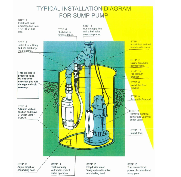
Make sure that Sump pump material inspection is done and are approved by the consultant.
Install pumps and arrange to provide access for maintenance including removal of motors, impellers, couplings, and accessories. The pumps should be lifted up to do the maintenance.
Suspend wet-pit-mounted, vertical sewage pumps from pit covers. Make direct connections to sanitary drainage piping.
Set submersible sewage pumps on basin floors. Make direct connections to sanitary drainage piping. Anchor guide rail supports to pit bottoms and sidewalls or covers.
Install pumps so pump and discharge pipe disconnecting flanges make positive seals when pumps are lowered into place.
Sump pit depth should be checked and as per approved shop drawings & builder work drawings.
Mark the pump location matching with proper guide rail location as per approved shop drawings and builder work drawings.
Install sewage pump basins and connect to drainage and vent piping. Brace interior of basins according to manufacturer’s written instructions to prevent distortion or collapse during concrete placement. Set basin cover and fasten to basin top flange. Install cover so surface is flush with finished floor.
Construct sewage pump pits and connect to drainage and vent piping. Set pit curb frame recessed in and anchored to concrete. Fasten pit cover to pit curb flange. Install cover so top surface is flush with finished floor.
Install packaged, submersible sewage pump units and make direct connections to drainage and vent piping.
Install packaged, wastewater pump unit basins on floor or concrete base unless recessed installation is indicated. Make direct connections to drainage and vent piping.
Support piping so weight of piping is not supported by pumps.
Confirming to the matching line of flange install the guide rail and supporting chain.
Ensure all support as per manufacturer recommendation and approved shop drawings.
All Piping to be done in accordance to approved drawings and pump out let size.
Gate valve and PRV to be installed properly.
All valves and major fittings to be supported properly.
Install relevant float switches.
Install the Control panel for the sump pump as per approved shop drawings and manufacturer recommendation.
Electrical Installation
A set of four level switches shall be provided to control the operations as under:
Low level switch to stop pumps.
Level 1 switch to start up pumps
Level 2 switch to start up “duty assist “pumps
Level 3 switch to raise a “high level “Alarm
Panel are installed on front door
- duty sector switch
- hand off auto switch for each pump
- run and trip lamps for each pump
- panel alive lump
- control circuit breaker failure lamp
Pump interface for building automation includes on /off status of each pump, power status and alarm on and also water level alarm.
Starting the Pump
Start pumps without exceeding safe motor power:
Start motors.
Open discharge valves slowly
Check general mechanical operation of pumps and motors.
Raise inspection for consultant approval after completion of the work.
Installation Checklist for Sump Pumps
Ensure approved material is used as per approved shop drawing & specifications.
Sump pump received and checked for damage.
Ensure all pit depth and area is cleaned /cleared.
Ensure Guide rail and supports are properly installed.
Ensure the chain is properly hanged to easily accessible place.
Check that lifting tools are installed and in-line with the pumps weigh / height etc.
All level float switches and dry run protections are properly installed.
Ensure that Pumps are properly installed.
Ensure all piping and its joints are pressure tested.
Ensure all supports and accessories are of stainless steel.
Ensure all HSE items are addressed properly.
Discover more from Method Statement Store
Subscribe to get the latest posts sent to your email.