The purpose of this project civil method statement is to define the procedure for the erection of tower crane. All work will be done in accordance with the requirements specified in the relevant specifications, technical procedures and approved drawings.
This Method Statement applies to the supply and delivery of tower crane components, the movements of related plant and equipment on site, and the erection and certification of the required tower crane construction works.
Contract documents
Project Specifications
Contract Drawings
Contractors Submittals
Project Quality Plan
Project Safety Plan
Tower Crane installation Manual
Drawing: Tower crane foundation details
Abbreviations
Engineer – Representative of engineering consultancy
ICL – Inspection Check List
IR – Inspection Request
ITL -Independent Testing Laboratory
ITP – Inspection and Test Plan
IR – Inspection Requests
MAT – Material Submittal
MEP – Mechanical Electrical Plumbing
MET – Method Statement
MIR – Material Inspection Request
MSDS – Material Safety Data Sheet
PPE -Personal Protective Equipment
PQP -Project Quality Plan
PTW -Permit To Work ( Mandatory for working at height or confined/enclosed spaces)
RA -Hazard Identification and Risk Assessment
RFIA – Request for Inspection and Approval
SPD – Shop Drawing
TBM – Temporary Bench Mark
Tower crane engineer is responsible for the compliance and successful execution of this work.
Tower crane erector is responsible for erecting the tower crane in a safe manner.
The mobile crane operators shall be responsible for ensuring the safe handling of all tower crane components at all times and for following the instructions of the slingers.
The QC Engineer is responsible for ensuring that the erection of the tower crane is carried out according to the project specifications.
The HSE Engineer is responsible for supervising the works to ensure full compliance with HSE requirements and procedures.
Equipment/specializing tooling
- Mobile Crane: 90 ton or 50 ton as applicable
- Flatbed Lorries
- Safety harnesses
- All necessary hand tools.
- Power tools (impact gun.)
Manpower Requirements
- Sub-Contractors Tower Crane Engineer
- Sub-Contractors Tower crane erector
- QC Engineer
- HSE Engineer
- Project Engineer
- Site Supervisor
- Riggers
- Helpers
- Tower crane operator
- Mobile crane operator
HSE Requirements for Crane Construction
Safety checks will be made prior to commencement of work in order to ensure that materials and equipment’s are in safe working order in accordance with project and site regulations
All personal will have had the site induction safety training.
All certificates and licences of mobile cranes and crane operators will be checked before reaction of tower cranes.
The erecting will be carried out strictly in accordance with the manufacturer’s recommendations, a copy of which will be on site.
All erectors will be experienced and competent in the erecting of this type of crane.
All erectors have received manual handling training and a manual handling assessment
When working at heights above 2 meters lanyard body harness will be worn and used when exposed to open edges, harness to be attached to crane mast sections.
A hazard zone will be set up around the working area using safety barrier tape, together with danger signs to prevent unauthorized persons entering the danger zone
Operations to take place only where weather and lighting conditions permit.
Maximum wind speed for crane operations will be 50 Km/Hr.
All operatives/erectors will be made aware of the contents of this method statement and associated risk assessment.
Any circumstantial changes on site will be notified to the project managers. A method statement field changed form will then be completed on site and signed off by crane supervisor.
Safety Equipment
All necessary PPE and safety gear will be worn at all times during the execution of work, in full compliance with safety requirements as below.
- Helmets
- Safety Shoes
- Hand gloves
- Safety Signs
- Safety Glasses
- Safety Harness
- High Visibility Vest
Tower Crane Erection Procedure
Tower crane Foundations
Setting out for location shall be done as per site plan. Excavation for crane foundation shall be carried out according to the approved drawing.
Blinding concrete shall be poured under the foundation. Shuttering and reinforcement steel shall be installed according to the approved drawing
The fixing angles shall be fixed in the exact location according to the drawing. Using the 50 ton mobile crane, one mast section weighing 1.555 tons shall be placed inside the fixing angles and secured in place to ensure the correct alignment of the fixing angles for the tower crane erection.
The mast section shall be aligned and checked for plumbness, squareness.
Concrete shall then be poured according to the approved drawing and left to cure for seven days.
The mast section shall then be removed by unbolting from the fixing angles and lifting out with the help of 50 ton crane.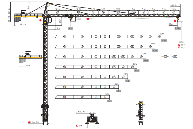
Preliminaries for crane erection
The crane crew on site shall familiarize themselves with site tasks to be undertaken.
The supervising Engineer shall ensure that the crane crew attends Site Safety Induction Training with the Main Contractor’s Safety Officer before beginning the crane erection work.
Components of the tower cranes shall be delivered to site by flat-bed trailer. Upon arrival at the site, the crane crew shall check and verify that delivered components are in proper working order and as commissioned.
The components will be offloaded from the trailer by the 50 ton mobile crane. Trailer and mobile crane shall be positioned as shown on the attached sketch, and the offloaded components stored in the designated area as shown. The crane operator shall work in coordination with the slingers to ensure safe lifting and slinging operations at all times.
The supervising Engineer shall report any damaged or missing crane components prior to starting erecting.
The crane crew shall prepare crane for erecting.
All listed operations below will be carried out by competent crane erectors and riggers supervised by erecting crew working from crane mast, top of jib and counter jib. Erectors shall wear safety harnesses at all times, which shall be securely attached to the crane during height work.
Basic Mast Section
The crane crew shall set up mobile crane for erecting of tower crane.
Using the 50 ton mobile crane, the crane crew shall install and attach the basic mast section to the fixing angles along with one (1) standard mast section
Slewing Ring and counter jib pre-assembly
The crane crew shall assemble the slewing ring platform and cathead in the designated assembly area and prepare them for assembly to the tower crane
The counter jib sections shall be prepared by the crane crew in the designated assembly area and assembled at ground level by use of the mobile crane. Total weight 2.54 Tons, total length 21.5m.
The crane crew shall connect the tie bars, on each side of the counter jib assembly. By use of pins. Total weight 740 kgs
Jib Assembly and Slewing Ring assembly to tower crane
The crew shall prepare the site for 90 ton mobile crane. Once the crane is in place, the assembled slewing ring and cathead shall be lifted into place and fixed by experienced riggers
The crane crew shall prepare the sections for the main jib in the designated assembly area.
The crane crew shall carry out the main jib assembly at ground level, with wooden blocks under each assembled jib section, by use of crane (max. weight of sections: 2.7 tons), in the location as shown on the sketch
The trolley (400 kg) shall then be added by the use of the 50 ton crane, and locked in place. The final assembly of the jib will then be completed.
The crane crew shall then assemble the tie bars, and attach them to the hooks on the assembled main jib.
Counter jib and jib assembly to crane
Using the mobile crane the counter jib assembly with the tie bars of total weight 3.28 tons shall be lifted to the top of cabin section (sketch-7), and fixed to the above by pins provided.
Using another crane of 50T capacity, the 4th tie rods (2 nos.), item 32, per sketch-5, shall be lifted nearest to the cabin top section. One tie bar shall be fixed on one side of cabin top section, and the operation repeated for the 2nd tie bar on the other side of cabin top section.
The main jib assembly shall then be lifted by the 90 ton crane to the level of the top cabin section and fixed with the pins.
The crane crew shall ready the counter weights, weighing 2.55 tons per block.
The first block shall be lifted by crane to the location of free edge of the counter jib boom and fixed in place.
The operation shall be repeated for the remaining counterweight blocks
The steel rope supplied by Manufacturer shall be run across wheel drum in gearbox winch all the way to end pulley, and back to trolley gear lock. It shall then be tightened and locked
Trolley and electrical assembly
All electric cable shall be run throughout the tower crane assembly and the power lines connected to the counter jib and main jib
The power supply panel shall be energized.
Installation of the trolley wire rope & hoist wire rope shall then be completed.
Hook blocks shall be installed, and all the limit switches and sensors as per manual powered and checked according to the requirements of the manual.
The hoist rope shall be extended from base unit by hand to tower head pulleys assembly
The hoist rope shall be passed around pulley assembly, one loop per pulley to a total of 7 loops. The operation shall be repeated for the other pair of 7 pulleys in the pulley assembly. The rope shall be terminated rope at the tower head hook and fixed in place.
Final assembly & Crane Construction Inspection
When all work is completed, further mast sections shall be installed by using the telescoping cage, until the crane reaches the maximum freestanding height.
Following completion of the assembly, full inspection and testing of the tower crane shall be carried out by a recognized 3rd party inspection agency. Any comments or discrepancies shall be rectified, until the crane is deemed fit for use and the 3rd party certificate can be issued.
When all above is satisfactory then the tower crane can be put in service.
Method for Creating & Closing cut-out for Climbing Crane Section
Repositioning the starter bars
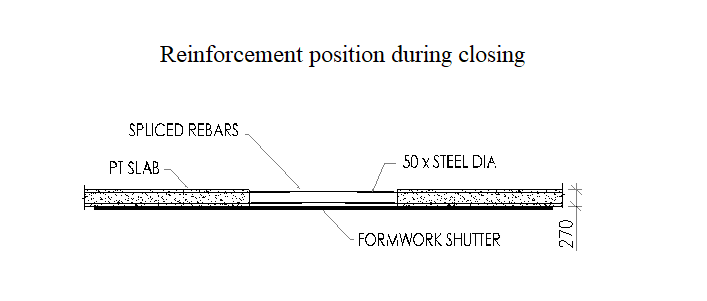
Starter bars for the crane opening slab shall be left in the cast slab in a bent-up shape for allowing the section of the crane to pass through, as shown in below figure.

During the course of the project these starter bars shall be kept protected by approved rebar corrosion prevention system. To prevent any water from dripping to the floor below a 50mm high fillet shall be made around the floor opening.
Cleaning of the Starter bars: Prior to casting the slab the starter bars shall be straightened and brushed clean using a wire brush. The sides of the opening shall be made rough by hacking to improve the bond between the new and the old concrete, and applying bonding agent.
Fixing of the Slab Formwork: The formwork shall be fixed as per the latest approved shop drawings. All Safety precautions shall be followed during the assembly process. When fixing the formwork care shall be taken to prevent any debris from getting in between the old concrete and the shutter.
Fixing Reinforcement: Once the formwork is inspected and approved by the Consultant the placement of the reinforcement opening in the slab shall commence.
The Slab reinforcement bars shall be fixed in accordance to the approved shop drawings and project specifications. The quantity, bar splices, spacing, rebar sizes and bending shall be verified. The fixing work shall be checked to ensure that all rebar were fixed properly in the proper location.
Sufficient bottom concrete spacers should be provided to maintain the concrete cover of reinforcing bars. The rebar shall be tied manually using tie wires. Enough chair bars shall be provided to maintain the correct distance between the top and bottom bars. The spacers shall be of sufficient strength to take the live and loads during the installation and the casting phases.
Requests for MEP installations shall be raised to check the sizes, locations and levels of Electrical works and Mechanical works embedded items.
An air compressor shall be employed to clean the area and remove all the accumulated debris.
Pouring of Concrete
Upon receiving the ready mix concrete the regular sampling and testing procedures shall be followed.
Pouring/ Depositing of concrete shall be done by Contractor’s competent site personnel’s and workers in accordance to the approved shop drawings and project specifications. Any concrete in the work which has partly hardened or which has been contaminated with foreign objects shall not be used.
When concrete placement is done using concrete pump the vertical drop of concrete shall not exceed 1.5m to prevent secretion. Vibrators shall be systematically applied, sufficient duration and intensity to compact the concrete thoroughly. Over vibration shall be avoided to prevent concrete segregation. A spare vibrator shall be provided for every three vibrators used for in case of breakdown. Concrete of an approved mix shall be used form an approved supplier.
Curing
Curing and protection of concrete shall comply with the guidelines given in the project specifications. Concrete protection and curing shall be done in such a manner as to prevent the evaporation of moisture from the concrete and injury of the surface. Immediately after the concrete has set, curing shall commence.
As soon as the concrete has stiffened sufficiently after not more than 24hrs, the surface shall be covered by absorptive mats of fabric and kept continuously wet for 7 days. Any curing compound materials used for concrete curing is subject for approval of the consultant.
Discover more from Method Statement Store
Subscribe to get the latest posts sent to your email.