Below is a brief HVAC method statement that covers the installation of Air Handling Units on a construction project.
Procedure defines the method used to ensure the AHU installation has been carried out as per contract specifications and manufacturer’s recommendations.
Method statement gives details of how the work will be carried out and how the health and safety issues shall be controlled.
References & Standards
- Contract Specifications
- IFC Drawings
- Inspection and Test Plan
- Project Safety Plan
- Project Quality Plan
- Project Logistics Plan
- QMS Procedures
- Job Safety Analysis JSEA
- Related International Standards and Codes
Material Handling & Storage
The air handling unit will be supplied on pallets unless otherwise specified, and will be offloaded from the delivery vehicle using a forklift or similar equipment.
Under no circumstances, any mishandling shall be allowed that can cause damage to the peripheral equipment of the AHU.
Should it be necessary to store AHU on construction site for longer period of time prior to installation, they must be stored in a clean, dry, secure area, where any possibility of damage to the air handling units is eliminated.
All units must be protected from building rubble, dust, dampness and heat. The unit exterior surfaces must be inspected on a monthly basis and any signs of corrosion, scratches etc. must be treated immediately.
AHU Pre Installation Checks
Before any installation work ensure that all equipment and accessories are inspected at site and have been approved as per the relevant MIR form.
Ensure the availability of drawings which are of latest revision and marked “Issued For Construction”.
Inspect the site and ensure that all necessary bases are installed as per shop drawings and specifications. Bases must be levelled there shouldn’t be any slope. There should be at least 100mm space at all sides.
Inspect the relevant area / plant room for any possible clashes with other services.
Inspect all materials and verify that they are undamaged.
Check for space clearance for transportation and installation of the AHUs and to carry out effective maintenance and to dismantle the unit modules as required. On the side and back of unit provide at least 600 mm access gangway for assembly and maintenance.
Check for the correctness of the markings and identification of all the sections prior to carrying out the installation. Orientations also to be checked.
Check and locate the condensate/ overflow drain.
Shifting, Lifting and Installation of Air Handling Units AHU
The unloading platforms in respective floors shall be constructed according to the load & dimensions of individual section of AHU’s by main contractor, the load and dimension shall be provided.
Capacity of tower crane must be verified first in order to ensure that it can withstand the weight of AHU’s sections.
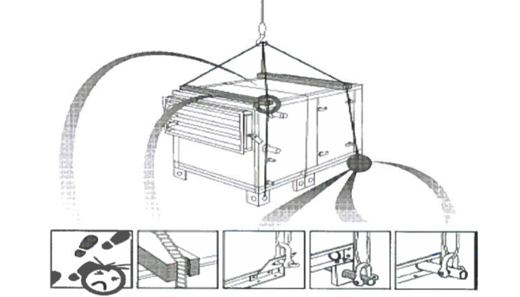
The AHU’s sections must be lifted as per the manufacturer’s recommendations i.e. from base frame, never lift the units by the coil connection, use battens to prevent damage to the top and side of the unit (see below sketch).
Dedicated group to operate the cranes / fork lift be only allowed & more personnel be maintained around for supporting / guiding the unit.
The unit assembly & installation shall be under the supervision of the manufacturer / supplier.
The AHU sections will be lifted to and offloaded to the platform at respective floors.
These sections should be then moved near and on to the approved neoprene pads mounted on plinth with the hydraulic trolleys/fork lift/pipe roller.
The hydraulic trolleys/fork lift/ pipe roller should be placed against the unit base frame at as possible as near to the centre of unit (see sketch below).
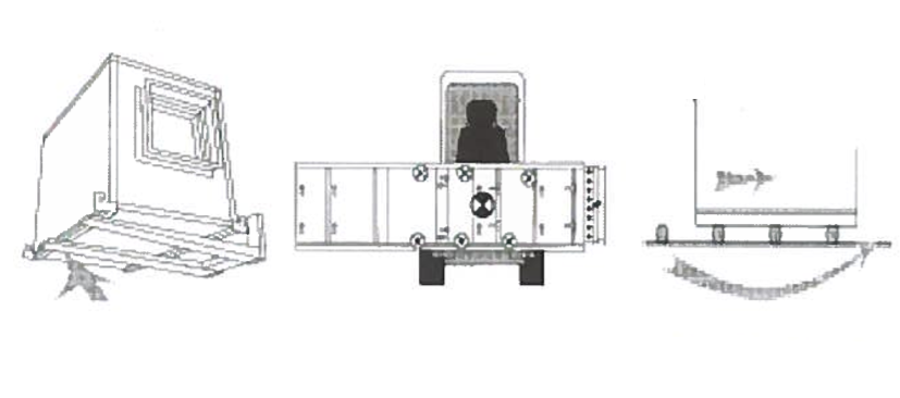
For safety reasons free standing units must be bolted to the foundation.
Avoid direct fixing of unit to the plinth rather use the fish plate around the centre of the unit, this will prevent units from movement in any direction (see sketch below)
Some of the upper sections and Heat Recovery Wheel (if any) will be lifted as mentioned in below method:
Drill the holes for fixing the anchors (avoid Post tension wires) and to fix the l/C channels on the soffit or as per AHU manufacturer instructions.
Provide support for channel at every 2 meter.
Channels should be installed at 6 meters extra from each side of the plinth in order to lift the sections.
After installing the channel place a push trolley (capacity based on the weight of lifting section) on each of the sides.
Chain block of suitable capacity must then be hanged from these push trolleys.
The lifting section then shall be lifted and moved to the designated location with the help of these push trolleys and chain block.
After reaching the location the sections must then be lowered into the Lower section of AHU.
Same procedure shall be followed to move other portion of upper section in place.
Mounting of the unit on its bases must be level and plumb to ensure proper drainage operation.
Lifting will be coordinated with the Logistics Manager and the Construction Manager.
Void be maintained below the ahu for house-keeping.
Assembly Procedure for AHU Sections
Check for the markings on the sections for identification and the sequence of assembly.
The drawings of the manufacturer should provide the information for the installation sequence of the sections.
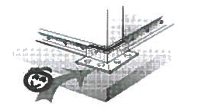
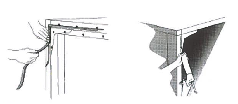
Sealing strip supplied by manufacturer should be attached to the inner edge of the module flange (see sketch below) then the sealing paste supplied by manufacturer shall be applied.
Set all the modules in correct position and as far as possible push them together. The bolt holes in the flange mounting should match.
The precisely aligned and parallel module flanges are then joined with the bolts supplied.
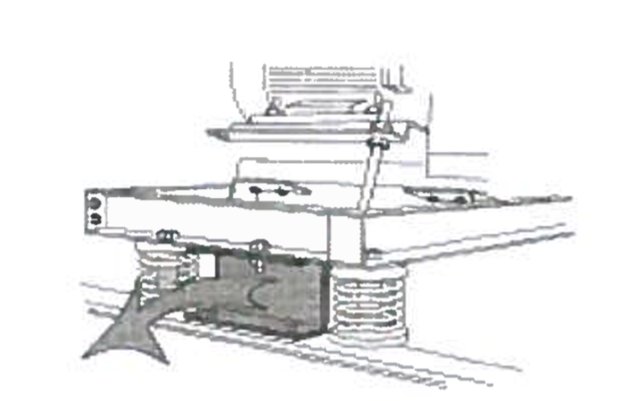
Locking devices at spring loaded dampers, fitted to the fan motor frame for transport safety purposes must be removed after the complete installation and assembly of units (see sketch below).
Ensure that both opening of cooling coils are plugged.
Any penetration of wires and cable shall be via proper sleeves or glands.
After installation of AHU protect/cover it properly to avoid any dust particle accumulating on unit.
Ductwork Connections: Connect all the ductwork as per Ducting Installation Method Statement. Ensure flexible connections are used and sealed.
Pipework Connections
Any protecting end covers shall be removed just before carrying out the respective piping installation.
Connect all the pipework as per piping installation method statement. Ensure flexible connections are used.
Control panel & isolators be installed in an accessible manner as per approved shop drawings.
Upon completion of the installation, the units will be visually inspected by the MEP / QA/ QC Engineer to ensure that the correct installation procedures have been followed and that units and components are securely supported in the prescribed manner.
Inspection request for the approval of consultant shall be submitted as per the ITP and using the inspection checklist for AHU installation.
Discover more from Method Statement Store
Subscribe to get the latest posts sent to your email.