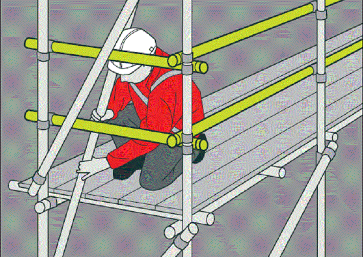
This document summarizes the general details for any kind of scaffolding formwork system as well as traditional wooden forms including Fabrication, Erection, Removal, Inspection and Striking etc.
The sequence of activities includes:
- Tying up reinforcement
- Concreting
- Curing
- De-shuttering
- Cleaning
- Stacking
This scope of works is for the following reinforced concrete works:
- Horizontal Elements: slabs, beams, staircases, etc.
- Vertical Elements: retaining walls, water tank walls, columns, internal walls, parapets, etc.
- This method statement is applicable to normal and post tension elements.
Regarding the procedures, not only the quality aspect of concrete formwork but the work methods will be described to a relevant extent so that the actual work process can be envisaged.
This document should be communicated reiterated, regularly reviewed and developed to suit changing condition, standards and technology as the site situation requires
Necessary Materials and Tools
– Formwork material (ply board, soft wood, nails, Tie Rods, Clamps)
– Base plate/Adaptor, Universal jack, Spigot jack, Drop head
– Standards, Ledgers, Bracings
– Props, U-head
– Support (Decking) Beam, Infill Beam
– Mould Release Oil
– Crane
– Skip
– Cutter
– Theodolite/Total station
– Dumpy Level
– Carpentry tools (hammer, hacksaw, crowbar etc.)
Formwork Roles and Responsibilities
Project Manager has the overall responsibility for the implementation of this method statement and shall well ensure that the approved Supplier for shuttering materials as well as other team members is aware of the requirements of the Method Statement.
Project Manager is responsible to coordinate with the company PRO and the local bodies for obtaining necessary and essential work permits – if any, for proceeding with the works.
Construction Manager/ Project Engineer will ensure that the Resources are available to carry out the scaffolding /shuttering works as scheduled.
Project Engineer/Site Engineer is responsible to carry out the form works as per approved Shop Drawings, Method Statements.
Site Engineer/Supervisor is responsible to ensure that the work has been carried out as per specifications & drawings and inspections are done as per contract.
Surveyor/Site Engineer/Supervisor is responsible for Setting out the area and measuring, monitoring and controlling the lines and levels.
QA/QC Engineer/ QC inspector is responsible to ensure that the work performed is in compliance with the approved method statement & other applicable requirements.
Safety Officer is responsible to ensure that all safety precautions are in place and that the personnel on site possess the necessary and essential PPE.
HSE Officer is responsible to ensure that essential work permits are available prior to the commencement of the shuttering work.
Scaffolding Formwork General Requirements
Form works shall be designed and constructed in accordance with applicable codes within the specified tolerances to the shape, lines, and dimension required by the design drawings(s).
Scaffolding Forms shall be coated with mould oil or release agent.
Form exposed corners to produce smooth, square, solid unbroken lines.
Provide chamfers for surfaces where indicated on drawings.
The column forms are fabricated and connected on the site using stripping pieces. Durable plywood panels of 18mm, which can withstand repetitive uses, will be used for the surface of formwork.
Working platforms with handrails will be attached to the side of the column forms for not only formwork but also other operations like rebar installation and concrete placement.
The climbing forms for walls will be manufactured. The whole load of the system will be supported by anchors cast in the wall concrete underneath and the system will climb along the climbing walls connected to the anchor bolts.
Temporary scaffoldings will be attached to the system at both inside and outside of the wall.
In addition, two stories of working platforms will be erected on the system to shut inside of the wall and to provide the space for workers and materials.
Durable plywood panels of 18mm thickness, which can withstand repetitive uses, will be used for the surface of formwork.
The plywood panels will be fastened on lattice girders extending vertically, and make up the unified single piece form panels.
For slab work, Shore/ support shall be provided for floor directly under slab being placed so that loads from construction above will safely transfer directly to these shores.
Formwork shall be struck without damaging, disturbing, or overloading the structure.
The minimum periods for striking formwork shall be as agreed with Engineer based on the compressive strength results on test cubes.
Calculations for formwork shall be submitted.
Scaffolding Erection procedure
Compact backfilling up to the bottom of grade slab.
CUPLOK system will be used as the form work type.
Wooden planks of minimum size 300mm wide x 50mm thick and 4mts long are be laid below the universal jack and socket (adjustable) base.
The top of wooden plan is maintained at -0.05m Level as per the design drawing.
Universal jacks with adjustable base are then placed apart at spacing equal to the length of ledgers (as per design drawing) starting from one corner of the building.
Standards are then fixed to the jack.
The ledgers of specified length are then clamped to the standards to form decking.
Height of the first deck of ledger is adjusted from plywood to the allowable depth mentioned in the drawing by adjusting the jack of adjustable base.
The second deck of the ledgers is then clamped to standards at height 1.5 M for first and third deck of ledgers is clamped to standards at height 1 M from the second deck.
Standards must be erected in true verticality.
Bracing of standards are done as shown in the design drawing at the specified locations.
Universal jack with drop head adapter are then fixed on top of the standards.
Upper jack is adjusted to achieve the required height of floor.
The decking beam 1.8 M is placed on the raised drop head as per the design drawings.
M infill beams are then placed resting on the decking beams at 0.35 M c/c (as per the design drawings).
18mm Marine plywood is then placed and fixed.
Removal Of Scaffolding Shutters For Reinforced Concrete
The minimum strength at the time of striking of concrete recommended by the project specifications is 75% of the characteristic strength.
Site cured cubes shall be crushed to determine the required strength at 3 days and 5 days.
The de-shuttering of vertical elements shall be done after 24 hours of casting.
Slabs & Beams
The time of de-shuttering of slabs shall be determined using 3day concrete test results.
These cubes shall be site cured and tested on the 3rd day (72 hours) of casting.
If the test results of cubes are 75% of the required strength then the slab shall be allowed to be de-shuttered.
In the case the concrete has not achieved 75% of the required strength; a second set of site cured cubes shall be tested at 5 days to see if the structure has achieved 75% of the strength.
The slab shall be de-shuttered after obtaining more than 75% (i.e. after 5 days) of the required strength and to be re-propped for 11(7)days and beams for 15 (8)days from date of cast.
| Element | Section 03110, | Proposed as per Section 031100, |
| Columns & Walls | 24 hours | 24 hours |
| Slab Soffits | 4 days | i.e. after 4 days (upon achieving 75% of strength) |
| Slab Re-props | 11(7) days | 11 days |
| Beam Soffits | 8 days | i.e. after 6 days (upon achieving 75% of strength) |
| Beam Re-props | 15(8) days | 15(14)days |
Scaffolding Site Inspection Plan
The exact date and time of form inspection prior to concrete placement or form closing will be informed to consultant as early as possible. However, because of very tight schedule of the whole project, timing of inspection needs to be flexible.
An approved formwork checklist will be provided to inspect the form erection. This sheet will be filled by the staff who not only performs the internal inspection but also attends the inspection by contractor.
Corrective actions on the erected formwork scaffolding will be directed to subcontractors based on the items on formwork checklist.
Plumb and alignment and other aspects of the formwork will be checked preliminarily just before rebar’s installation and finally before concrete pouring and paid full attention during concreting operation works so that any changes fall within the specified tolerances.
If there occurs slanting or deflection of the formwork over the tolerance range, it may lead to discrepancy of embedded items location. In this case, an appropriate way to accommodate installation of steel beams or eyebrow trusses will be determined based upon consultation with consulting engineer.
Health, Safety, Environment HSE Requirements
The entire form work will be carried out as per the guidelines established in the Project Specific HSE Plan.
Utmost importance shall be given to safety of personnel and protection of existing above /underground services.
It will be ensured that the personnel involved are thoroughly aware of the “Name of the contracting company”/ Employer Safety regulations.
To achieve the above the following shall also be ensured:
- Tool Box Meetings will be conducted before starting the works.
- All personnel will be provided with suitable Personal Protective Equipment.
- Required permits will be obtained from the Engineer/ authorities concerned before starting the works.
- Plant & Equipment’s shall be fully tested & certified by an independent testing agency. Copies of certificates shall be submitted to Engineer
- All pneumatic / lifting equipment’s including booms, slings; chain blocks etc. shall be fully tested & certified by an independent testing agency. Copies of certificates should be available.
- Scaffolding and working platforms will be checked for its safety.
Discover more from Method Statement Store
Subscribe to get the latest posts sent to your email.