Below document describes instructions and guidelines for PDA Testing On Bored Piles / Micro Piles. The PDA/CAPWAP system was developed by Pile Dynamics Inc, Ohio, USA and has been in use for more than 15 years.
PDA field data acquisition and computer unit has its own in-built self checking system and all force and acceleration transducers are fully calibrated in advance.
PDA test is well recognized in the following international standards:
- ASTM (American Standard of Testing Materials) standard D4945-12
- ICE Piling Specifications (UK)
- BS8004 (British Standard Foundation code – 7.5.2)
- Canadian Foundation Engineering Manual (1992 – Canadian Geotechnical Society).
Pile Monitoring and Preparation
Pile instrumentation and monitoring will be performed using the PDA/CAPWAP system according to the ASTM standard D4945-12.
The system involves a Pile Driving Analyzer (PDA), which is manufactured by Pile Dynamic Incorporated, USA.
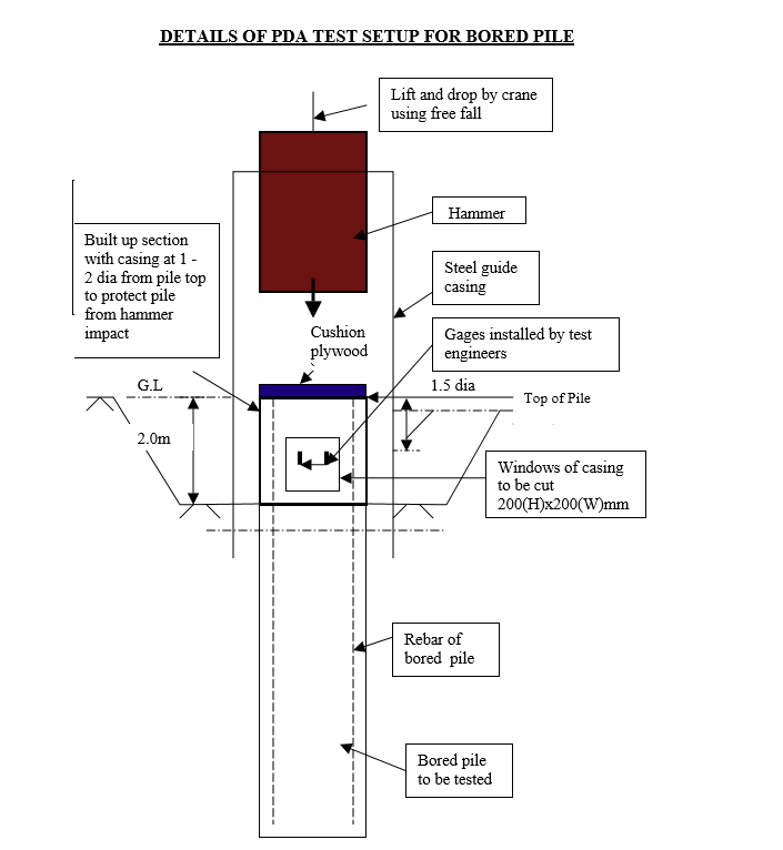
Measurements of the force and velocity signal induced in the pile during pile driving are collected by strain and accelerometer transducers, which are fixed near the pile head (at least 1.5 diameter away from pile top).
For each blow struck to the pile the PDA signal processor conditions the output from these transducers and passes it to the processing section of the PDA.
The PDA has an in-built program, which calculates over 30 pile driving variables based on the data obtained from each blow. These variables include maximum pile top force, displacement and velocity, estimates of pile static and dynamic capacity.
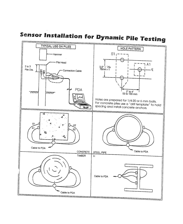
In order to conduct PDA testing, transducers need to be attached to the pile to be tested.
PDA force and velocity transducers will be attached at approx. 1.5 dia below the head of the pile and at two locations diametrically opposite each other.
At each location one force transducer and one accelerometer will be attached to the pile.
Special precautions will have to be taken to conduct proper PDA test on bored piles such as:
- Build up section of pile should have higher strength concrete preferably grade 40 or above.
- Minimum strength of concrete before testing should be 30N/mm2 or more.
- Bored pile to be tested to be encased with steel casing at the top section (1m – 2m from pile top) of pile in order to strengthen the concrete pile for hammer impact.
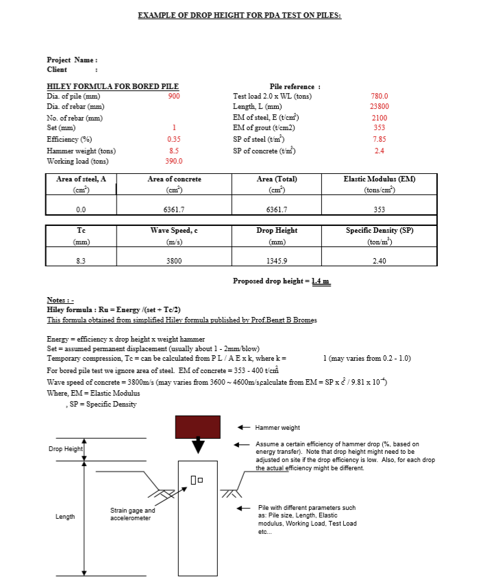
- Drop height of hammer proposed to be carefully calculated using dynamic Hiley formula by specialist testing firm to prevent overstress during testing.
- Hammer to be aligned vertically to prevent eccentric stress developed at hammer impact.
- Hammer guide is recommend to be used.
- Proposed drop height will have to be adjusted (revised/increased) on site if stress measured during testing is too high/low after first hammer blow.
- Note that desired static capacity may not be achieved if energy imparted onto pile is insufficient.
The PDA monitoring equipment will be set up in the vehicle or shaded protected area at certain distance from the pile.
A main cable connecting the PDA unit to the pile top transducers will be run from the unit to the gauges.
The piles are recommended to be tested to 2 times working load for working pile. This is to prevent any overstress in the pile during hammer impact.
The ultimate static capacity should be higher than 2 times working load.
Soil skin friction set-up effect may be taken into consideration in the long term and therefore pile capacity can increase with time.
Data Processing and CAPWAP Analysis
Under each hammer blow, the analyzer will be triggered and data acquisition will begin at this time.
The PDA automatically processes each blow recorded during monitoring and can display computed values of over 30 pile variables on command.
PDA automatically checks each blow for pile integrity and provides a warning of any damage detected along the length of the pile.
In the event of any damage being detected the PDA will automatically indicate the location of the damage and the severity of the damage.
Pile top force and velocity signals recorded in the field will be processed and a representative blow will be selected for further analysis using the CAPWAP suite of computer software.
After the completion of the CAPWAP analysis the PDA field estimates of static capacity can be refined and analyzer data can be calibrated to the CAPWAP analysis.
This will effectively refine the real time PDA estimates of static capacity, which will be available for subsequent piles monitored.
CAPWAP will also give you the skin friction distribution and end bearing resistance of pile and predicted load settlement curve under static loading.
PDA and subsequent CAPWAP analysis will indicate the amount of static capacity that is actually mobilized during any one blow delivered to the pile during testing.
In order to fully mobilize all available pile static capacity a pile set in excess of 3 – 4 mm per blow is required.
Should the pile set be less than 3 – 4 mm, or the soil quakes be in excess of the normal 3 – 4 mm then not all of the static pile resistance will be mobilized during any one blow and the subsequent CAPWAP and PDA analysis will under predict a true static capacity of the pile.
This provides some in-built conservatism to the capacities indicated by the PDA and CAPWAP system in the event of small set being recorded.
If this is the case the PDA system is regarded as a proof test, not a full load test.
Reporting of PDA Testing
On completion of all field work, a final report covering all aspects of the pile monitoring and analysis work will be prepared.
This report will incorporate results of the PDA monitoring, and results of all CAPWAP computer analyses.
The results of the CAPWAP analyses will be compared to the PDA results and correlations will be drawn between the CAPWAP data and the PDA field monitoring results.
Results from PDA test will be calibrated against the static load test results if results are available, to obtain a better correlation and comparison with the static.
Results which can be obtained in report are as follows:
Static capacity of piles (compression or tension) mobilized.
Simulated load settlement curve under static load.
Pile integrity (any defects, necking, crack or any irregularities in pile shaft)
Discover more from Method Statement Store
Subscribe to get the latest posts sent to your email.