Below is precise plumbing method statement that shall ensure that the plumbing accessories i.e. valves installation is done as per contract requirements and manufacturer instructions.
The method also gives details of how the work will be carried out and the health and safety issues and controls shall be implemented.
Materials, equipment and components when arriving on site will be stored as recommended by the manufacturer and proper storage/shelter will be provided.
When valves have been stored for more than 3 months, open & close the valves. Repeat for every 3 months of storage.
Store valves in a way that no heavy loads are applied to the valve bodies.
Where applicable, the faces of each valve should be covered with cardboard, plywood or similar sturdy material to prevent damage to the seat face, disc edge or the valve interior.
Pre Installation Procedure
Ensure the materials, equipment and components are as per approved material submittal and as per technical specification.
Ensure that the drawings are current and marked “Issued for Construction”.
All equipment and components will be installed in strict compliance with each manufacturer’s recommendations.
Ensure the areas of installation are cleared and free from debris, dust & dirt prior to commencing the works.
Materials will be moved to the work site in a safe manner and shall not block access / egress to the site.
Ensure that adequate number of tradesmen and proper tools are available at site.
Valves shall be compatible for piping & flanges. Valves have been engineered so that the critical disc dimension at the full open position will clear the adjacent inside diameter of most types of piping, including schedule 40, line pipe, heavy wall, etc.
Ensure valve is suitable for service conditions e.g. pressure, temperature, and service media.
Check that internal pipe diameter has sufficient clearance for valve disc to be fully operated.
Check that the pipe flanges are parallel and on the same centerline, before installation.
Do not remove dust caps protectors, until just before valve is fitted, to prevent ingress of dust / dirt etc.
Valves Installation Method
All Valves should be installed in a straight run of pipe of the same nominal size with arrow pointing in the direction of Flow. It may be oriented at any angle. The gaskets must be assembled so that they are concentric with the pipe bore and do not intrude into it, or the measurement accuracy may be reduced.
Make sure all pipelines & flanges are clean.
Any foreign material such as pipe scale, metal chips, welding slag, welding rods, etc. can obstruct disc movement or damage the valve, therefore ensure cleanliness.
Align the piping and then spread the pipe flanges so that the valve body can be easily placed between the flanges without contacting the pipe flange.
Where the valve is connected to a check valve or pump, use an expansion joints to ensure that the disc does not interfere with the adjacent equipment.
Check to see that the valve disc has been positioned to a partially open position with the disc edge approximately 1/ 4” to 3/8” from the face of the seat. (Approximately 10° open)
Remove dust caps/ flange protectors, where fitted.
Installation should be designed to provide adequate means of draining and venting to avoid harmful effects such as water hammer, vacuum collapse, corrosion and uncontrolled chemical reactions and to permit cleaning, inspection and maintenance in the correct manner.
Threaded joints shall be made using fine quality jute & joint adhesive compound.
Piping system shall be designed to reduce the risk of fatigue due to vibration of pipes.
Pipework opened to allow free valve entry with the disc in semi-closed position.
Best practice is to have the disc in the 10% open position while installing. Refer below image.
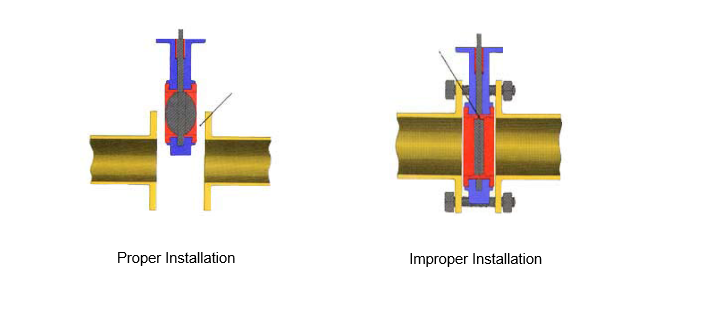
Pipework not spread sufficiently could tear rubber seat. Disc open position will hit flange and score disc. Closed position causes distortion.
Valve in semi-closed (10% open) position:
a) protect disc edge
b) reduce rubber interference during installation and start-up and
c) help reduce initial torque build-up.
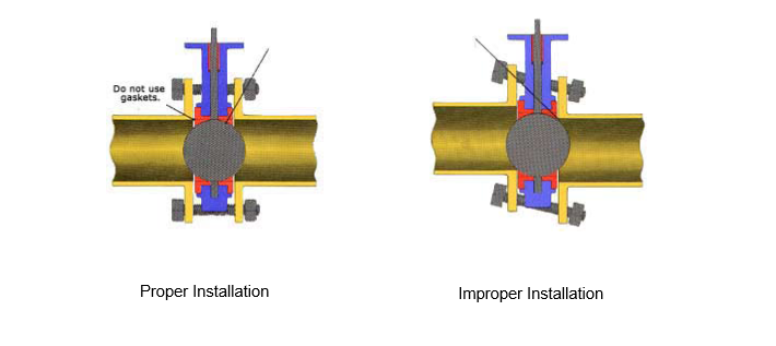
Disc should be returned to full open position after pipe / flange alignment.
Incorrect pipe alignment will cause interference between the disc edge, creating leakage and excessive torque for opening valve. Refer below figure.
Ball valves may be fitted in vertical, horizontal or inclined pipelines.
Flow may be in either direction and the valve may be any way up, on its side or upside down.
The position chosen should allow easy access to the operating mechanism.
It is important to leave access to the gland nut, if fitted.
Threaded end valves are supplied with taper threads and, with the use of thread sealant, will give a pressure tight seal.
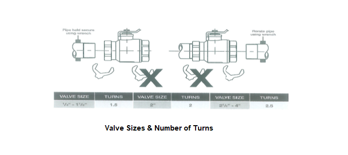
To avoid distortion of the valve when fitting and tightening pipe, the valve must be held securely using the flats provided at the end of the valve to which the pipe is being fitted.
Care should be taken to avoid “pipe ending”. This condition that occurs when the pipe is screwed in too far resulting in distortion to the valve seat.
The male thread on the pipe must have fully formed undamaged threads.
Screw the pipe into valve & hand tighten, then tighten by the number of turns shown in below figure. (up to one conditional turn is permitted for alignment)
Tight valve shut off at high working pressures will require closing torques which are higher than can be obtained manually with the hand wheel, and will require the use of a closing bar or wrench.
A guide to the torques required for a 16 bar pressure drop across the valve are shown in below table.
This torques may be applied without risk of damaging the valve.
|
Valve Size |
Maximum Closing Torque |
|
|
DN |
NPS | NM |
|
65 |
2 1/2 |
45 |
|
80 |
3 |
60 |
|
100 |
4 |
110 |
|
125 |
5 |
130 |
|
150 |
6 |
220 |
|
200 |
8 |
420 |
|
250 |
10 |
650 |
| 300 | 12 |
650 |
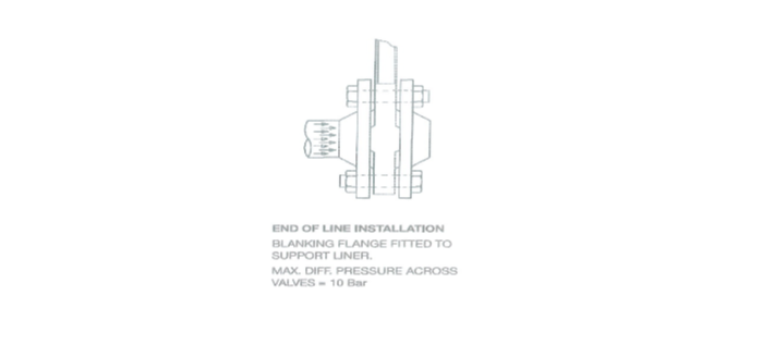
When a valve is used for end line service, a blanking flange should be fitted. Refer to figure below.
In these instances, ensure that system pressure does not exceed limitations as detailed below.
Perform the pressure testing as per the standard requirements and project specifications.
As per project requirements the pressure tests of all pipe work including valves to be carried out 1.5 times the working pressure.
Raise an inspection request for consultant/client approvals, including the local authority approval where applicable.
Discover more from Method Statement Store
Subscribe to get the latest posts sent to your email.