The purpose of this document is to specify the procedure for excavation backfilling and trench preparation for installation of 132 kV cables and fiber optic Cables.
Roles & Responsibilities
Project Manager: Lead all construction activities and enforce strict adherence to all procedures.
Site Manager: Lead the construction activities at site and report to the Project Manager.
Field Engineer: Ensure that all related works are carried out in accordance with the approved drawing and project specification. Report to the site manager.
QA/QC Engineer: Responsible for the necessary quality control implementation by following the customer specification.
Supervisor: Supervise field installations and report to the field engineer.
HSE Officer: Ensure that all the site activities are carried out in accordance with the project health and safety plan.
Necessary Tools and Equipment’s
Hand tools for Excavation
- Hand Shovels
- Plastic Buckets
- Wheel Barrows
Equipment’s
- Jack hammer for removing hard strata like asphalt and Rocks
- Crane & Buckets – shall be used to remove excavated material from pit where pit is not accessible by other methods.
- Plate compactor, Mechanical Tampers to compact the backfilling materials.
- Air compressors
- Water tankers
Excavation & Backfilling
Preparations and Preconditions
Permit to Work (PTW) shall be raised for the excavation clearly mentioning the location of work, size of excavation and levels.
Excavations area shall be surveyed and marked to the lines and levels as shown on the drawings.
The area of excavation will be cordoned off using safety barricading to stop trespassers.
Assign sufficient banks men, helpers and supervisors at the site prior to start of excavation.
Required sign boards such as “DEEP EXCAVATION” “MEN WORKING” “DANGER” and warning boards will be placed to indicate the excavation work.
Ensure the working area at any confined space is free from any Hazardous Gas by proper Gas testing using the Gas testing instrument.
Proper temporary supports shall be provided to the adjacent structure prior to start excavation.
Fences and minor structures of any character or upon within the limits of the works and not necessary for the construction shall be removed carefully and stored neatly for reinstating after the construction works.
If any Survey points, bench marks, boundary stones and markings falling on the area shall be removed only with the client’s written consent and shall be stored and reinstated according to their instructions.
Check the area of excavation to find out any underground facilities other than listed in topographical survey by:
Using appropriate detective equipment, such as cable detector, metal detector etc.
Check existing exposed excavation nearby area to find out existing underground facilities.
Refer available As-built drawings from the consultant, other agencies, other contractors doing projects nearby areas and mark in the area.
Take trial/ test pits to find out existing underground pipes, structures.
Check the indication marks, signs, manholes nearby area and find out the path of services.
Trial Pit and Excavation Procedures
Prior to star of any excavation, the area shall be checked for the existing services/utilities by obtaining the approvals with reference to the relevant drawings.
The necessary excavation activities shall start only after getting the notice intent from the client / customer.
Excavation of the trial pits shall be done manually as per the size indicated in the approved drawings up to the required length and level.
In open areas the excavation shall be carried out by using the machineries, the exact location of each trench and pit being subjected to the prior approvals.
Manual excavation will be carried out to expose the existing utilities, if any, which has to be identified.
The trenches shall be kept dry during cable installation operation. The contractor shall deal with the dispose of water so as to prevent any risk to the cables and other materials.
Contractor shall provide suitable dewatering methods as explained in section 6.0 while performing the works according to the scope of work.
The required control measures shall be developed and implemented while performing the works and more importance will be given for public safety and environmental issues.
While performing the work the trenches shall be straight, free from any sharp objects/edges likely to injure the cable or accessories and filled with soft sand and sieved sand to form smooth bedding before the cables are laid.
The contractor shall take the necessary precautions to prevent damage to the road or ground surface due to a slip or breaking away from the side walls of the trench including the pedestrian safety as well.
The vehicle entry shall be restricted on the specified work area by prior approval from the concerned agencies.
Where ever there is a crossover of the existing services/utilities, these shall be protected with utmost care with the prior permission of concerned authorities and approved methods.
The contractor shall obtain the necessary approval from the client / consultant or the concerned authorities to according to the scope of the work.
Excavate the area by using only hand tools as per the markings and levels with proper protection of sides. If excavation depth exceeds 1.2 m proper shoring and shuttering should be provided as per the safety norms or the excavation shall be stepped, wide enough to get stable slope on sides of wall from soil sliding.
Excavations in sand shall be to a slope of 1:3, one vertical to three horizontal.
If any permanent slope is to be kept in the sand it shall be stabilized by one of the following means,
- Mass concrete blinding
- Cement/sand mixture
- Bituminous/cement mixture
Trim and form the edges of soil to profiles and levels as indicated in drawings.
If the excavation level is below the local water table level suitable dewatering system (well point method and/or pump and sump method, refer section 6.0) shall be designed and installed in such a way that alterations and extensions to the system during operations are possible.
For Rock excavation hard excavation shall be carried out by ripping, excavation, wedging, chiseling using jack hammers, or by other recognized methods approved by consultant. Blasting will not to be adopted under any circumstances for rock excavation.
In trench excavation the bottom width of at least in 800 mm plus the dimension of pipes, conduits, ducts etc. to be installed.
The bottom of the excavation shall be levelled and trimmed to receive the permanent works.
Bottom of the excavation shall be moisture conditioned to + 2% of optimum and mechanically compacted to a density of not less than 95% of the maximum dry density.
Precautions shall be taken to protect the bottom of the excavation and, if the bottom of the excavation becomes unsuitable either by exposure to weather conditions, water, or due to any other reasonably foreseeable event, it shall be removed and replaced with suitable materials.
Provide proper rigid barriers around excavations include provision of ladders, emergency escape way, adequate side slopes or shoring and shuttering, detours.
If fossil content is noticed during excavation shall be brought in notice of the OWNER.
The top width of excavation shall be increased or depend upon the depth of excavation, It is required to provide suitable slope to side of excavation to avoid soil sliding, then the top trench width shall be increased accordingly by step cutting method. If the top width of excavation is restricted due to existing facilities then protect the side of excavation with proper shoring.
If the bottom of excavation is loose strata then excavate 300 mm more to select fill materials to form a hard and compacted grade strata for construction.
If the bottom of excavation is below the water table level, provide proper shoring prior to excavate below the water table level then excavate 300 mm more to fill Aggregates or Gravel to form a hard grade strata.
Excavation Adjacent to Underground Services
Excavation near the existing electrical cables, instrumentation and control cables, sewer line, gas lines and any other service line shall take all necessary precautions to protect the services with proper supports & covers.
All existing structures, foundations, pipes and cables, if any, which are to be incorporated into the final work, shall be adequately protected from damage.
All underground services located during excavation shall be mapped for consideration during construction of the works.
If any underground service is noticed other than specified in the area during excavation shall be brought in notice of the client.
Excavation shall not be carried out adjacent to or near existing building foundations, without suitable shoring/sheet piling.
Over Excavation
In case excavations executed beyond the established levels, backfill the over excavation with lean concrete or other approved material.
The volume corresponding to the over excavation shall not be carried out adjacent to or near existing building foundations, until suitable shoring/sheet piling has been installed.
Stockpiles and Disposal
Excavation material shall be removed, stockpiled or deposited away from the excavation area for reuse, or disposed in the approved dumping area as directed by OWNER/Engineer’s.
Debris, rocks and unusable materials shall be removed on daily basis from the site to approved dumping area or final destination whether in the work or in the waste areas, including any necessary temporary stockpiling and the additional loading and transporting.
Only permitted materials or selected materials from excavation shall be stored or stockpiled for re-use.
Refilling of Excavation
The refilling of excavations shall be started as soon as practicable after the permanent works have been tested and approved by the consultant.
Refilling of trenches over pipes shall be done by hand to a depth of 300 mm above the crown of the pipe with dune sand or lightly compacted selected excavated material free from large stones, rock, clay lumps or other substances which may cause damage to the permanent works.
Refill the leftover portions with suitable backfilling material in 300 mm per layer which shall be fully compacted by mechanical tamper/plate compactor/roller and tested in accordance to project requirements.
Backfilling of Trenches
Backfilling area shall be backfilled with approved material compacted in layers by suitable equipment like plate compactors, vibratory roller compactors, etc., until the specified density has been obtained to the satisfaction of the client.
Compacting shall be carried out with special care by means of mechanical tampers of a type approved by client to avoid damage to structures.
Areas to be backfilled shall be prepared so as to obtain a soil density at least equal to 95 percent of Standard Proctor test (ASTM D 698).
Backfilling Materials
Backfilling materials shall be free from stones or rocks larger than 50 mm, or other material which might prevent proper compaction or cause the compacted fill or embankment to perform inadequately.
Backfilling materials shall be free from fossil content, clay, vegetations and its roots, waste materials, Material containing gypsum or other soluble salts greater than the allowable limits.
Following classified materials shall not be used for backfilling.
- Organic material, logs stumps and perishable materials.
- Material susceptible to spontaneous combustion.
- Materials with undefined properties.
- Materials having moisture content greater than the maximum specified.
- Building rubble and domestic and industrial wastes.
- Soils and rock susceptible to deterioration/change of their properties.
- Clay, silt and other loose or soft soils not in accordance with compaction criteria.
- Dredged material.
- Rock materials
Filling of Materials
Fill material shall be spread and compacted in 300 mm layers, with a compacted layer thickness not exceeding 300 mm where mechanical compactors like vibratory plate/drum compactors are used.
The thickness of fill material shall not exceed 150 mm where manual compaction methods are adopted.
If the thickness of loose fill layers required to exceed 300 mm written approval including methods of compaction shall be required from the client.
If the surfaces receiving fill layers is smooth, then scarified to obtain a good friction/key between the new fill layer and the sub grade.
Rock fill or aggregate fill materials shall be deposited under water with the client’s permission. Fill materials like cohesive soil (i.e. soils that possess low shear strength, are plastic and compressible, deforms plastically under constant load, changes volume in the presence of water) shall not be permitted deposit under water.
Where swamps, bogs or other similar wet areas must be traversed by the works, they shall be drained as directed by the client according to the material and conditions encountered.
Prior to the formation of embankments, fill, etc. any unsuitable material occurring on the site shall be removed to such depths and widths as may be directed by the client and approved excavations shall be properly backfilled with suitable and approved excavated materials and shall be deposited and compacted to the satisfaction of the client. Similarly, soft or weak spots encountered will be removed and, as with any voids, will be backfilled as specified.
Final layer of backfilling shall not contain soft rock fragments exceeding 50mm upon placement to the satisfaction of the OWNER/ENGINEER’S.
Trench backfilling containing pipes shall be properly packed at the sides with sand which shall be well rammed with narrow wooden rammers before filling further.
The filling shall then be carried up to 150 mm above any sand or concrete surround with fine selected material and well watered and rammed.
Remainder of the trench shall then be refilled in layers not exceeding 300 mm thickness, watered and rammed until the ground is thoroughly consolidated.
No mechanical rammer shall be used with 300 mm of the top of any pipe or surround and material shall not be drooped from a height.
The top surface area shall be dense and level without any protruding rock fragments in excess of 50 mm, recesses or soft spots, to the satisfaction of the client.
Tolerance level shall be maintained as per the specifications
Excavated materials may only be used for backfilling after obtaining satisfactory approved lab test results; otherwise fill materials shall be imported to the site.
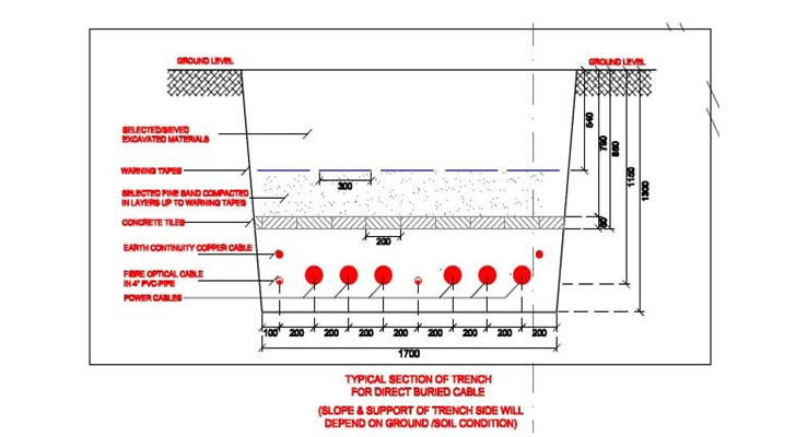
Formation of Cable Trench
The formation of the trench shall be in accordance with applicable standard and specifications.
The trench shall be excavated upto the required depth of 1.3m from the existing ground level.
Dune sand bedding shall be done for a thickness of 150mm at the bottom of the trench using TR tested and approved dune sand, prior to the installation of cables.
Cables and the 4” uPVC pipes for the FO Cables are laid over the dune sand bedding
Sand Filling
TR tested and approved sand (Max 120°C cm/W) is filled in the trench to the required level as per approved drawing.
Sufficient Water is poured to match the required Moisture content and to get 95% MDD
Cable protection tiles are laid above the dune sand filling
Final Backfilling
Ensure the Concrete Cable Tiles are securely placed.
Selected sieved materials from the excavated soil shall be backfilled for a thickness of 250mm above the cable protection tiles. Care shall be taken to avoid stones and boulders mixing with the backfill material.
Install 132kV Cable Warning Tape at a height of 250mm from top of the concrete cable tiles
Backfill to the required level in similar way.
Ensure Proper Compaction of soil is done after every 150mm layer laid.
Reinstate the area as to its original situation.
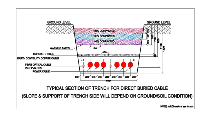
Compaction of the Back Filling Material
The required density shall not be less than 95% Modified Proctor under Roads and pavements. This shall be obtained by compaction in layers by means of rollers and/or dozers, applying as many passes as may be necessary and to the approval of the consultant.
Sweet water or portable water from a source approved by the company shall be sprayed on the placed material prior to compaction where necessary to achieve the optimal moisture content.
Brackish or salt water is not allowed to be used in compaction.
The density of each placed and compacted layer shall be established by testing prior to the placement of subsequent layers. If the results of test indicates that the required density is not being achieved further tests shall be carried out.
Compacted Soil Testing
All the testing shall be carried out to the satisfaction of client.
All such tests shall be carried out at a laboratory approved by clients. Results of all tests shall be approved by client. Filling of subsequent layers shall not commence till approval from consultant is obtained.
Field density testing shall be in accordance with BS1377 at a minimum frequency of one per 5000 m2 per layer shall be achieved.
Tolerance limit for the permanent finished earth work shall be included as stated in specifications.
The top surface area of the finished surface shall be dense and level without any protruding rock fragment in excess of 50 mm, recesses or soft spots, to the satisfaction of client.
Discover more from Method Statement Store
Subscribe to get the latest posts sent to your email.