
This procedure is applicable to all natural gas pipeline underground installation works at any kind of project and aims to ensure that all works are carried out to comply with the applicable acts, regulations and by laws i.e. Local and international code of Practice for the Installation of Fuel Gas Piping Systems and Appliances, Occupational Safety and Health Act and Regulation, any other authority having jurisdiction over the scope of works.
Below are the activities covered in this procedure:
- Storage management
- HDD work
- Soil excavation work
- Soil backfill work
- MDPE pipe and fittings installation
- Carbon steel pipe and fittings installation
- Anti-corrosion tape wrapping work
- Coring work
- Sleeve insertion works
- Gas cock installation
- Leakage testing
- Housekeeping
Roles and Responsibilities
Engineering Manager is responsible of all activities related to the project. He is available on request or as per job requirement.
Project Manager is responsible for the execution of the project. He is available full time at site.
Project Executive assists Project Manager in the execution of the project. He is available on request or as per job requirement.
Site Supervisor is responsible of the manpower planning onsite. He is responsible to obtain all permits required prior to the job, holds toolbox talk and JSA with workers and ensures work complies with the design. He is also responsible for chairing daily progress meeting onsite. He shall act as the immediate authorized person in the absence of the Project Manager.
Welder – He is responsible of MDPE pipes and fittings fusion, carbon steel sch40 pipe and fittings welding and conducts leakage testing.
Fitter – He is responsible for general works at site.
Machinery Tools & Equipment
Specialist contractor shall provide good working equipment’s in order to complete the work safely. MEP contractor shall erect site storage facilities to store all work materials, tools and equipment’s. Contractor shall supply but not limited to the following equipment’s:
- Electro-Fusion Welding Machine
- Pipe Clamp
- Diesel Generator
- Welding Set
- Thread Machine
- Drilling Machine
- Speed Cutter
- Rotary Hammer
- Grinder
- Hacker
- Coring Machine
Horizontal Directional Drilling (HDD) work
To carry out Horizontal Directional Drilling (HDD) work for underground MDPE pipe installation across the main roads/crossings.
Prior to carrying out HDD works, supervisor shall discuss and verify with the main contractor and consultant the area/path to be drilled.
Drilling path designed with consideration to the position of existing utilities, accessibility of drilling rig and geographical site, and shall be at least 3 feet below the road.
Details of utilities shall be marked on plan, should necessary final adjustment will be made at site.
Radio detection shall be used to finalize the path. Trial hole shall be excavated to verify the base of the underground utilities.
Warning signs and colored bunting shall be erected at locations of overhead power cables.
Work area shall be barricaded with warning signs erected.
Horizontal distance and cross sectional profile of the proposed bore shall be determined with measuring tape and dumpy level.
Drilling path shall be marked on the ground.
High viscosity drilling fluid shall be used to prevent the collapse of borehole during drilling.
Drilling fluid viscosity shall be monitored and maintained at Funnel Viscosity 40 secs/quart.
A (1.5 m x 1.0 m) x 1.0 m depth pit shall be dug at the entry and exit point to cater for cuttings and fluids.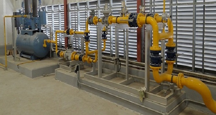

Commence drilling operations by attaching a 3” diameter fluid jet drill head with sensor to the drill rod.
Drilling trajectory shall be monitored at every 3m by Digitrak Electronic tracking system.
Locator technician shall inform drilling operator should drill head strays off course.
Adjustment shall be made by the drilling operator.
At exit pit, drill head shall be removed and replaced with a fluid jet reamer.
Reamer shall be retracted through the drilled hole – at doing so borehole will be enlarged and more cuttings will be removed.
Different diameter reamers shall be used to enlarge borehole in steps to a max of approx. 30 percent than pipe size.
MDPE pipe will be laid on rollers after being string up.
After final reaming, pipe will be attached to the last reamer and swivel and will be pulled into borehole.
Upon installation pipe ends shall be capped to prevent foreign particles ingress.
Site shall be cleaned and reinstated and drilling rig demobilized.
Soil Excavation Work
To conduct soil excavation work to lay underground MDPE pipe and underground carbon steel pipe (c/w anti-corrosion tape).
Prior to carrying out excavation works, subcontractor shall discuss and verify with the main contractor and consultant the area/path to excavate.
Permit to work shall be applied and made available at site.
Toolbox talk shall be held prior to starting the excavation work.
JCB excavator shall be mobilized, unauthorized personnel kept out of the excavation area.
Trench shall be excavated as per approved drawing. It shall be prepared as such that the pipe lays on a firm, continuous bearing on the bottom.
After achieving the desired depth and width excavator shall be demobilized and site cleaned in preparation for pipe laying.
MDPE & Carbon Steel Gas Piping and Fittings Installation
Welders shall make sure that all pipes and fittings are dry, free from burrs, suspended matter and oil.
Prior to jointing the pipes with electro-fusion machine, the MDPE pipe shall be aligned properly by clamp.
For more detailed information on electro-fusion joint of MDPE pipes and fittings, refer to machine operation procedure.
Carbon steel pipes and fittings installation
Pipe Cutting
Pipes shall be cut to desired length based on shop drawings:
Carbon steel pipe length shall be measured by measuring tape and marked at the desired length based on endorsed shop drawing.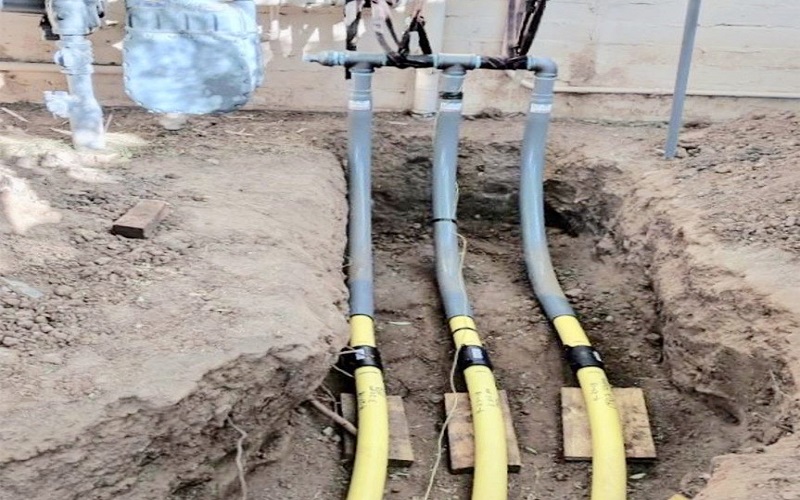

Speed cutter (on Portable Cut-Off Saw) shall be set on clean, dry, stable surface, without the presence of flammable elements and connected to the power supply.
Wear proper apparel. Do not wear loose clothing, gloves, necklaces, rings, bracelets or other jewelries which may get caught in moving parts. Nonslip footwear is recommended. Wear protective hair covering to contain long hair. Safety glasses shall be used. Face or dust mask shall also be used while operating the machine.
Pipe shall be laid on the speed cutter, pipe marked position adjusted to the speed cutter cutting wheel.
Pipe position shall be fixed at 90 degree with the base of speed cutter and hold down by clamps.
Before using the tool on pipe, let it run for a while.
Watch for vibration or wobbling that could indicate poor installation or a poorly balanced wheel.
Switch on, wait until wheel attains full speed and lower gently to cut the pipe on marked position.
Watch out for flying sparks when operating. They can cause injury or ignite combustible materials.
Do not overreach. Keep proper footing and balance at all times.
Do not touch the workplace immediately after operation; it is extremely hot.
Never leave tool running unattended.
Turn power off. Do not leave tool until it has come to a complete stop.
Power off and disconnect power supply.
Anti-corrosion Tape Wrapping
All underground, floor/wall embedded carbon steel pipes should be wrapping with anti-corrosion tape to keep the pipes corrosion free.
The pipe surface shall be free of mud, oil, grease or any others foreign material that will prevent the joint coating system from bonding to the steel pipe surface.
Visible oil and grease shall be removed with suitable solvent.
The steel surface shall be dry prior to the application of the joint wrap tapes.
KEROSENE shall NOT be used for cleaning the pipe joints.
Wrapping shall be applied under hand tension or using a hand-wrapping machine capable of maintaining even, constant tension across the width of the tape.
The wrapping shall be 55% over lap.
Screw Thread Making
To fabricate male screw end on pipe, pipe shall be threaded by threading machine:
The threading machine shall be set on clean, dry, stable surface, without the presence of flammable elements and connected to suitable power supply.
Wear proper apparel. Do not wear loose clothing, gloves, necklaces, rings, bracelets or other jewelries which may get caught in moving parts. Nonslip footwear is recommended. Wear protective hair covering to contain long hair.
Be sure switch is OFF before plugging in. Carrying tools with your finger on the switch or plugging in tools that have the switch ON invites accidents.
Do not overreach. Keep proper footing and balance at all times. Proper footing and balance enables better control of the tool in unexpected situation.
Insert the pipe into the threading machine so that the cutting mark is located about 12 inches to the front of the speed chuck jaws.
Insert workpieces less than 2 feet long from the front of the machine. Insert longer pipes through either end so that the longer section extends out beyond the rear of the Threading Machine.
To avoid equipment tip-over, position the pipe supports under workpiece.
Tighten the rear centering devise around the pipe by using a counter clockwise rotation of the handwheel at the rear of the Threading Machine. This prevents movement of the pipe that can result in poor thread quality.
Secure the pipe by using repeated and forceful counterclockwise spins of the speed chuck handwheel at the front of the threading machine. This action “hammers” the jaws tightly around the pipe.
SMAW Welding of Gas Pipeline
Shielded Metal Arc Welding (SMAW) or stick welding is a process which melts and joins metals by heating them with an arc between a coated metal electrode and the carbon steel pipe.
Wear welding mask /welding goggle and welding glove.
Arrange cables to one side and away from the operator.
Do not coil or drape cables around body.
Keep welding power source and cables as far way from operator as practical.
Connect work clamp to pipe as close to the weld as possible.
Bevel the pipe end into 30 Degree by using grinding tools, also remove any oxidation and mill scale.
Align the pipe/fitting in jointing position with 1.5mm gap between 2 elements.
Set-up the welding machine with proper amperes and select an electrode.
Electrode angle should be 75° – 80° according to welding position.
Electrode outer coating, i.e. flux, assists in creating the arc and provides the shielding gas and slag covering to protect the weld from contamination.
The electrode core provides most of the weld filler metal.
Weld the joint by moving electrode along the pipe end bevel at the correct speed, the metal deposits in a uniform layer will seal the joint (bead).
Leakage testing of Gas Piping System
Pneumatic leakage testing shall be conducted by welder prior soil backfilling for MDPE pipe and cement patching for embedded carbon steel pipe.
Testing pressure is determined by 1.5 times of operating pressure or minimum 5 psig.
Leakage testing shall be witnessed by main contractor and consultant.
Testing record must be documented and endorsed by main contractor and consultant.
Temporary Bracket Installation
Nail bracket shall be applied to all embedded carbon steel pipes for temporary positioning before cement plastering:
Fabricated pipes shall be aligned into pipe groove.
2 pieces of nail (approximately 3mm Ø x 25mm length) shall be derived into the wall/slab and nail head secured with slim wire to hold pipe in centre.
Care to be taken not to scratch/damage pipe.
Coring Works
It is required to make a core hole on floor, slab or beam by coring machine to allow pipeline to be installed through.
Prior to carrying out coring works, discuss and verify coring position and obtain permit from main contractor and consultant.
Mark core position and fit/mount the coring machine in position by using wall plug.
Equip the coring machine with proper size of core bit and provide suitable current supply.
Switch on the coring machine and spray water on the core hole during process.
Turn off coring machine after bit core is through the slab/beam.
Dismantle the wall plug and clean the coring site.
Sleeve Insertion Works
Tools and equipment’s to be prepared i.e. measuring tape, PVC pipe etc.
The level of PVC to be inserted at the wall slab shall be measured and marked.
PVC pipe shall be cut using pipe cutter and pipe’s butt sealed with masking tape.
The completed PVC pipe shall be inserted into the floor beam mold.
Tighten the PVC pipe with the wire at the mesh wire.
Soil Backfill Work
Backfilling work after the installation of underground MDPE pipe and underground carbon steel pipe shall be done as under:
Upon installation, the underground piping shall be covered with sand bedding.
Tracer wire, warning slab, protection slab shall be laid to mark the position/as protection to the installed piping system.
On top of the protective concrete slabs, the trench shall be filled and compacted with soil.
GI pipe sleeve is required as a protective sleeve for road-crossing pipes.
Gas Cock Installation
Gas cock shall be installed at each gas outlet after the pipeline system installation is complete.