

This plumbing method statement covers the installation of strainers. Procedure defines the method used to ensure the installation has been carried out as per contract requirements and best industry practices. It gives details of how the work will be carried out and how the health and safety issues and controls shall be implemented.
Roles and Responsibilities
- MEP package manager will be the overall responsible for complete site works.
- All Site Engineers & approved specialist plumbing contractor will be responsible for installation of strainers for chilled water & plumbing piping systems.
- Foremen will control and guide the workers and will report to site engineer.
- Safety Engineer/Officer will be responsible for implementation and assurance of safety and environmental requirements (JSEA).
- Quality Control engineer will be responsible for the assurance of the method statement and inspection and test plan (ITP).
Tools & Equipment
- Drill machine
- Portable electric drill
- Forklift
- Step Ladder
- Platform scaffolding
- Welding Machines
- Threading machine
- Measuring Tape
- Helper’s tool box
- Spirit Level, Water tube & Plumb
- Hammer
- Hacksaw
- Marker and masking tape (consumables)
- Pipe Wrench (Adjustable & Fix)
- Bench Vise
- L- Key Set
- Pipe Cutter
The minimum Personal Protective Equipment (PPE) on site is:
- Hard hat
- Safety boots
- High-visibility vest
- Gloves
- Goggles/Glasses
- Safety Belts
Delivery, Handling and Storage
Materials, equipment and components when arriving on site will be stored as recommended by the manufacturer and proper storage/shelter will be provided. Materials and equipment should not be dropped onto hard surfaces and should not be dragged along the ground.
Loading and unloading will be carried out by hand or fork lift if necessary. Adequate protection will be provided to prevent mechanical damage during off-loading.
Storekeeper will inspect for any damage during shipping, handling and storage and will be responsible for proper storage as per the requirement.
Provide protective covering sheets over the item or keep the manufacturer protective covering for the materials until the time to move the materials to the required location.
Materials, equipment and components received at site will be inspected by the consultant in accordance with approved material submittals.
Pre-installation Checks
Ensure the materials, equipment and components are as per approved material submittal and as per technical specification.
Check and make sure that the drawings are current and marked “Issued for Construction” or as recommended, drawings shall be approved by consultants.
All equipment and components will be installed in strict compliance with each manufacturer’s recommendations.
Ensure the areas are cleared and free from debris, dust & dirt prior to commencing the works.
Materials will be moved to the work site in a safe manner and shall not block access / egress to the site.
Ensure that adequate number of tradesmen and proper tools are available at site.
Make sure that all machine surfaces are free of defects and the inside of the strainer is free of foreign objects.
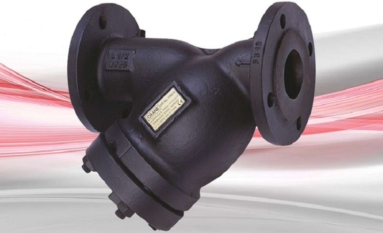
Ensure the identification plate & body marking must be correct to ensure that the right strainer is being installed.
Check and ensure “Y” Strainers’ pressure rating is correct for the system.
Ensure strainers are suitable for service conditions. E.g. pressure, temperature etc.
Remove dust caps/ flange protectors, where fitted.
Make sure that the piping system shall be so designed to reduce the risk of fatigue due to vibration of pipes.
Ensure that the end connections are threaded or designed for soldering or brazing.
Make sure that pipelines are straight and not at an angle or offset.
If the strainer has flanged ends, be sure the flanges of the connecting piping are square with the pipe so that no undue stresses are put on the strainer or piping when tightening flange bolts. Tighten in sequence, crossing to opposites.
Make sure that the strainer does not exceed the allowable limits of pressure.
Ensure that the strainer installation shall be done in a way to provide adequate means of draining and venting to avoid harmful effects such as water hammer, vacuum collapse, corrosion and uncontrolled chemical reactions and to permit cleaning, inspection and maintenance in the correct manner.
To ensure strainers work at best efficiency, valves must be installed so that the strainer basket is in the direction of flow. An indication arrow is cast on the valve body.
If strainers are threaded, these are equipped with taper threads and with the use of a thread sealant will give a pressure tight seal.
To avoid distortion of the valve when fitting & tightening pipe, the valve must be held securely using the flats provided at the end of the valve to which the pipe is being fitted.
Strainers Installation Procedure
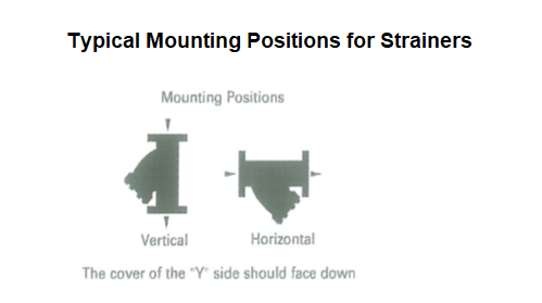
For horizontal pipelines, the strainer shall be installed such the blowdown connection is pointed downwards.
Refer to Figure below for Horizontal & Vertical mounting of Strainers.
Strainers will be installed with the direction arrow on the body coincident with the direction of flow in the pipeline.
For vertical pipework the flow direction shall be downwards only.

For Flanged end Strainers, the flange bolting should be tightened gradually in a back & forth clockwise pattern.
Sealant shall be applied to a Threaded end strainers. Figure below shows to Typical Flanged End & Threaded “Y” Strainers.
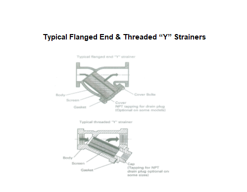

Install the strainers with sufficient room so that the strainer element can be withdrawn from beneath in a downwards direction.
Strainers shall be installed in a piping system whose normal pressure & temperature do not exceed the strainer ratings.
Refer to Table below:
Operating Pressure /Temperature Rating
|
PN |
Non-shock Pressure at Temperature Range | Non- shock Pressure at Max. Temperature |
|
13.8 |
13.8 bar from -10°C to 66°C |
9.7 bar at 220°C |
|
16 |
16 bar from -10°C to 120°C |
11.8 bar at 230°C |
|
25 |
25 bar from -10°C to 120°C |
21 bar at 230°C |
| 40 | 40 bar from -10°C to 120°C |
33.6 bar at 230°C |
Strainers must be provided with adequate support.
Adjoining pipework must be supported to avoid the imposition of pipeline strains on the strainer.
Strainers must be installed with cartridge/ cap projection pointing downstream.
Inlet & outlet piping centerlines should be aligned to avoid damage on the housing.
Observe end connection spacing, given in table below.
For flanged units, do not rely on bolts to draw connecting pipes to strainer, on the side of less, rather than more spacing to minimize stresses on the housing welds.
Allowance for NPT thread, or socket weld insertion will further reduce spacing.
|
Nominal Size (inches) |
End Connection Spacing Dim A (Inches) | PVDF Y Strainer (psi) | PTFE Y Strainer (psi) |
|
1/8” |
7.4 | 150 |
65 |
|
¼” |
7.4 | 150 | 65 |
|
3/8” |
7.4 | 150 |
65 |
|
½” |
7.4 | 150 |
65 |
| ¾” | 9.9 | 150 |
50 |
|
1” |
9.9 | 150 |
50 |
|
1 ¼” |
10.6 | 150 |
35 |
|
1 ½” |
10.6 | 150 |
35 |
|
2” |
12.2 | 100 |
30 |
|
3” |
14.7 | 60 |
25 |
|
4” |
17.3 | 60 |
N/A |
Perform the pressure testing as per the standard and project specification requirements.
As per project requirements the pressure tests of all pipe work including valves to be carried out at 1.5 times the working pressure.
Make a check request to the consultant/ client for inspection as per format given by the consultant. Also obtain the local authority approval if necessary.