

In the 1950’s, E.A. Smith of the Raymond Pile Driving Company studied wave propagation on slender rods, and developed a numerical analysis method to predict the capacity versus blow count relationship and investigate pile driving stresses.
The model mathematically represents the hammer and all its accessories (ram, cap, cap block), as well as the pile, as a series of lumped masses and springs in a one‐dimensional analysis.
Soil response for each pile segment is modeled as viscoelastic‐plastic.
All components of the system are realistically modeled.
The analysis begins with the hammer ram falling and attaining an initial velocity at impact.
This method is the best technique for predicting the relationship of pile capacity and blow counts (or set per blow), and the only method available to predict driving stresses.
Improvements to Smith’s method to incorporate a thermodynamic diesel hammer model and residual stresses.
The wave equation approach is an excellent predictive tool for analysis of impact pile driving, but it has some limitations.
These are mainly due to uncertainties in quantifying some of the required inputs, such as actual hammer performance and soil parameters.
Types of Wave Propagation Pile Testing
There are different types of Wave Propagation pile testing; three of these tests are covered in this pile testing method statement:
1. High Strain Dynamic Testing
2. Low Strain Pile Integrity Testing
3. Cross Hole Sonic Test
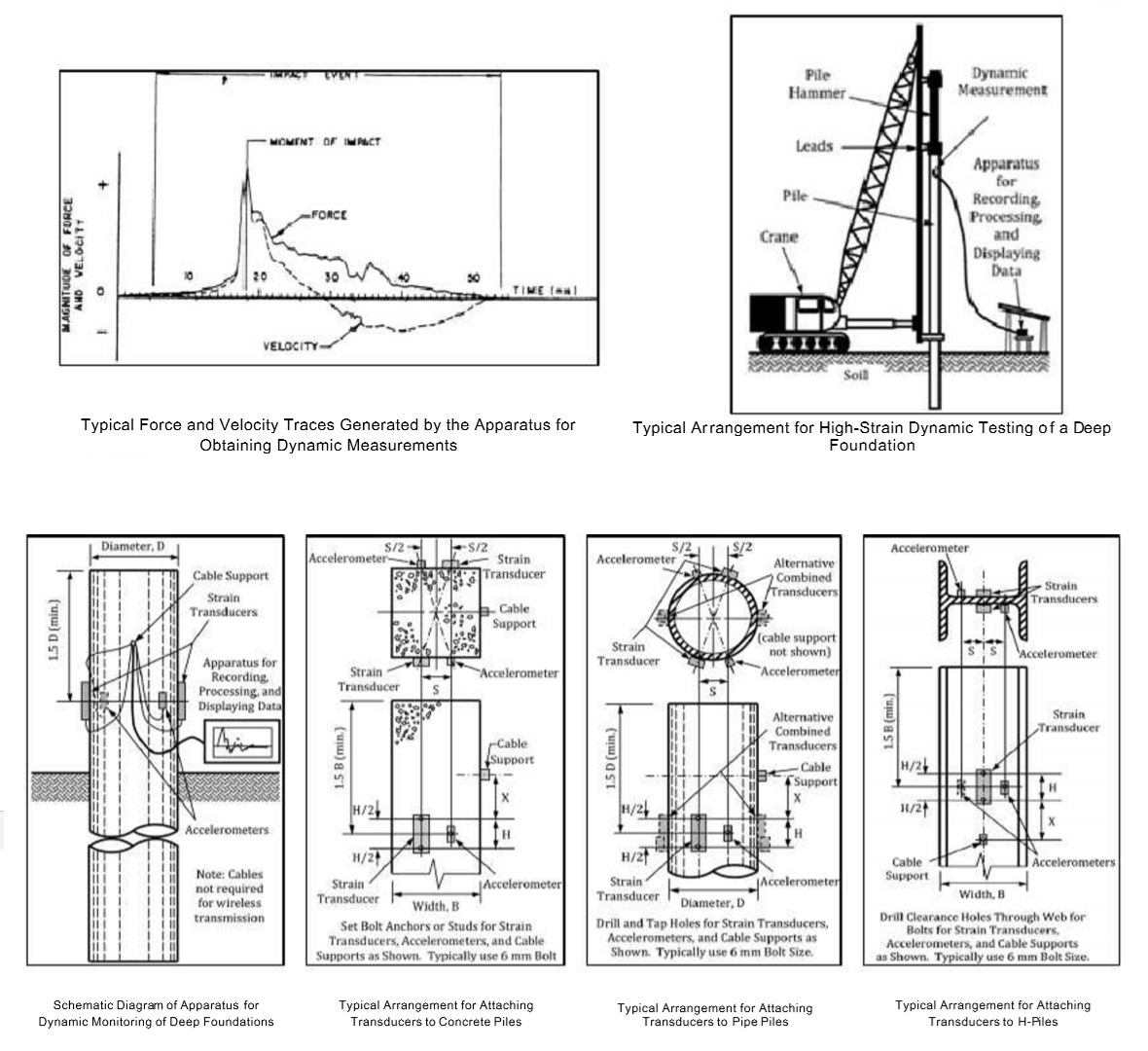
High Strain Dynamic Pile Load Testing
High Stain Dynamic Load Testing (HSDLT) of piles is a fast and effective method of assessing foundation bearing capacity that requires instrumenting a deep foundation with accelerometers and strain transducers and analyzing data collected by these sensors.
The procedure is based on the case method of pile testing and is standardized by ASTM D4945‐08 Standard Test Method for High Strain Dynamic Testing of Piles.
It may be performed on driven piles, drilled piles and other cast in place foundations.
In addition to bearing capacity, Dynamic Load Testing gives information on resistance distribution (pile resistance and end bearing) and evaluates the shape and integrity of the foundation element.
The foundation bearing capacity results obtained with dynamic load tests correlate well with the results of static load tests performed on the same foundation element.
Frequency of this test is one pile to represent the entire site including current and future pile installation. Engineer may increase number of piles (Tests) as required. Typically testing includes 5% to 15% of the total number of the working piles.
Prerequisites for High Strain Pile Test
The static axial capacity of piles typically changes as time elapses after pile installation, possibly increasing (setup) or decreasing (relaxation), depending on the soil or rock properties and the pore water pressure and soil structure disturbance induced by installation.
This behavior may affect both driven piles and cast‐in‐place piles. The Engineer may specify a waiting period between pile installation and High Strain Dynamic Load testing to investigate time effects.
The waiting period may range from 3 to 30 days, or longer, based on testing (for example re‐driving piles) or prior experience.
Also the concrete to be sufficiently hardened, which can be confirmed by the concrete test cube reports.
Method of High Strain Dynamic Load testing
High‐strain dynamic testing is performed by obtaining and analyzing records of pile force and velocity under drop weight or Hammer impacts for evaluations of pile load carrying capacity, structural integrity, and load‐movement and pile‐soil load transfer relationships.
Allow sufficient time for driven and cast‐in place deep foundations constructed of concrete to gain adequate structural strength prior to testing.
If a permanent casing is not used as a feature to construct the test pile, then a pile top extension, consisting of a thin walled casing or equivalent, shall be used to extend the test pile. Means to insure flat, level, (axial to test pile) and solid concrete pile top. Concrete should be level with, and slightly above the casing. If the top of the test pile is below grade, then remove surrounding soil so as to completely expose a test area as described above. Windows on at least two opposite sides of the test pile may have to be cut off in the steel casing to reach the concrete. (Not Applicable for a pre‐cast pile or steel Pipe Pile).
In cases where casing is not present, smooth (by grinding) areas around the pile circumference such that proper sensor attachment can be accomplished.
Sensors (at least 2 nos.) shall be attached to the exposed concrete or steel casing in a secure manner as to prevent slippage under impact.
For concrete piles or concrete filled pipe piles, place a pile cushion made of plywood or other material with similar stiffness on top of the pile. For concrete filled pipe piles, the concrete must completely fill the pile top so that the impact is transferred through the pile cushion to the concrete.
Dynamic tests performed during the initial installation of a driven pile typically monitor the performance of the impact device, the driving stresses in the pile, the pile integrity, and relative changes in capacity. If the test results are used for static capacity computations, then dynamic measurements should (also) be performed during restrikes of the deep foundation, after waiting a period of time following the initial installation sufficient to allow pore water pressure and soil strength changes to occur.
A drop weight of approximately two percent (2%) of the anticipated test pile capacity, (one percent may be sufficient for piles with rock sockets); higher percentages are helpful when practical and when available or specialized Diesel/Hydraulic Hammer can be used for pre‐cast piles. The impacting surface of the drop weight should have an area between 70 and 130% of the test pile top area. The shape of the ram weight should be as regular as possible (square, round, hexagonal, etc.). A top cushion consisting of new sheets of plywood with total thickness between (50 to 150 mm.) shall be used to absorb the hammer impact.
At least two (2) hammer impacts should be applied to the top of the pile. First drop height should be minimal to allow the Testing Engineer to assess the testing equipment, the impact system and the stresses on the foundation. Subsequent impacts can then be applied by utilizing sequentially higher drop heights until either stresses in the foundation are excessive or the pile permanent set for the applied impact exceeds 2.5 mm.
Based on the measurements from strain or force, and acceleration, velocity, or displacement transducers, this test method obtains the force and velocity induced in a pile during an axial impact. The Engineer may analyze the acquired data using engineering principles, CAPWAP and judgment to evaluate the integrity of the pile, the performance of the impact system, and the maximum compressive and tensile stresses occurring in the pile and after assessing the resulting dynamic soil response along the side and bottom of the pile, the Engineer may analyze the results of a high‐strain dynamic test to estimate the ultimate axial static compression capacity.

High Strain Dynamic Testing Report
The report for Dynamic Load testing shall include the following information:
General Information
- Project info.
- Client info.
- Pile info (Length, Type, Diameter, Casting/Driving date …etc.).
- Hammer info.
- Comments and recommendations about the pile(s) capacity.
- Equipment Certificates and Calibrations sheets.
Graphical out puts drawing
- Force vs. time curve.
- Velocity vs. time curve.
- Load vs. settlement curve.
- Load Distribution.
Detailed Tables outputs
- CAPWAP Summary
- Soil Model Parameters
- Extrema Table
- Dynamic Resistance Table
- General Summary
- Case Method
- Pile Profile and Pile Model
- Static Load table
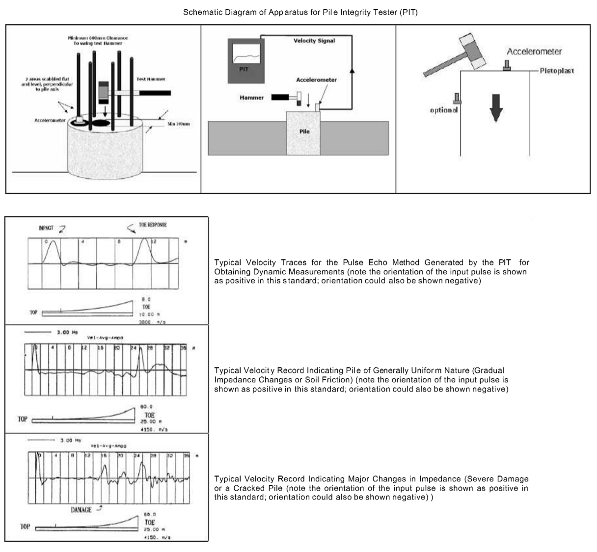
Low Strain Pile Integrity Testing
Low Strain Pile Integrity Test (LSPIT) is echo or seismic method of assessing the integrity of piles, it has been used since the 1970’s to check the integrity of piled foundations and is standardized by ASTM D5882‐07 Standard Test Method for Low Strain Integrity Testing of Piles.
The system measures the velocity response of a pile to a force input generated by a small hammer. The system is rapid in operation and can be used to check the depth of both pre‐cast and cast‐in‐situ piles. The possible causes of intermediate responses can also be assessed.
Frequency of this test is one pile to represent the entire site including current and future pile installation, client may increase number of piles (Tests) as required. Typically testing includes 100% of the total number of the working piles
Prerequisites for Low Strain Pile Test
For cast‐in‐place concrete piles or concrete filled pipe piles, perform the integrity testing no sooner than 7 days after casting or after concrete strength achieves at least 75 % of its design strength, whichever occurs earlier.
Ensure that the pile head surface is accessible, above water, and clean of loose concrete, soil or other foreign materials resulting from construction.
If the pile head is contaminated, remove a sufficient pile section to reach sound concrete.
Because proper pile top preparation is critical to the successful application of this method, if necessary, prepare small areas by a hand grinder to provide a smooth surface for motion sensor attachment and impact.
Standard Test Method for Low Strain Integrity Testing of Piles
The accelerometer must be firmly affixed to the pile top in order to measure the high‐frequency motion of that surface during impact and reflection. For best results, the accelerometer should be bonded to the pile top. Petroleum jelly works nicely in cold weather. Other adhesive materials such as plastic clay or bowl sealer wax can also be used.
The motion sensor should be placed at or near the pile head using a suitable, or temporary, thin layer of bonding material (that is, wax, Vaseline, putty etc.) so that it is assured that it correctly measures the axial pile motion (transducer axis of sensitivity aligned with the pile axis).
Motion sensor is placed generally near the center of the pile. Additional locations should be considered for piles with diameters greater than 500 mm.
The low strain impact should be applied to the pile head within a distance of 300 mm from the motion sensor. If the pile head is not accessible, as when already integral with the structure, the sensor(s) may be attached to the side of the pile.
Signals from the motion sensors shall be conveyed to the Pile Integrity Tester (PIT) for recording, reducing, and displaying data as a function of time. The PIT includes a graphic display of velocity, and a data storage capability for retrieving records for further analysis.
Record the measurements from several impacts. Average the suitable records of at least three impacts and apply necessary amplification to the averaged record. The records from the individual impacts or the averaged record, or both, should then be recorded. The averaged, amplified record then can be evaluated for integrity.

Low Strain Pile Integrity Testing Report
The report for Pile Integrity Test shall include the following information:
General Information
- Project info.
- Client info.
- Pile info (Length, Type, Diameter, Casting/Driving date …etc.).
- Assessment (Pile Acceptance criteria)
- Equipment Certificates and Calibrations sheets.
Graphical out puts drawing
- Velocity vs. time curve for average impacts for each individual pile.
- Pile profile plot (in case of flaw or damage).
Detailed Tables outputs
Piles Rating (AA, AB, ABx, PFx or PDx)
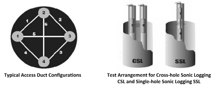
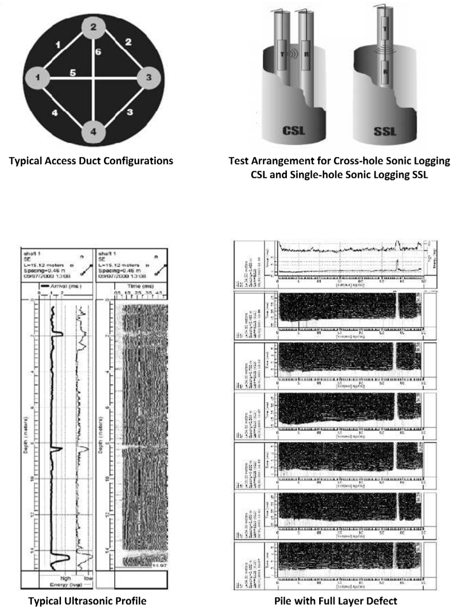
Cross Hole Sonic Pile Test Method
Cross‐hole Sonic Logging (CSL) is a NDT method which involves ultrasonic signal transmission through the pile between two parallel water filled access tubes.
The access tubes are often tied to the steel cage and cast permanently into the pile.
Total number of access tubes typically depends on the diameter of the pile.
A transmitter probe and a receiver probe are lowered to the bottom of the pile in separate access tubes.
Measurements of the signal transmission are collected approximately every 5 cm as the probes are raised to the top of the pile.
The cables attached to the probes are pulled through calibrated encoder wheels which can accurately determine the depth of the probe during testing.
A collection of measurements from one access tube to another are called a profile.
Profiles are collected from all combinations of access tubes.
The test method is described in ASTM D6760‐08.
Frequency of this test is one pile to represent the entire site including current and future pile installation. Engineer may increase number of piles (Tests) as required. Typically testing includes 50% ‐ 100% of the total number of the working piles.
Prerequisites for Cross Hole Sonic Test
The access ducts shall be supplied and installed during construction by or in cooperation with the contractor of the deep foundation element to be tested. The total number of installed access ducts in the deep foundation element should be chosen consistent with good coverage of the cross section.
As a guide, the number of access ducts is often selected as one duct for every 0.25 to 0.30 m of deep foundation element diameter, spaced equally around the circumference.
A minimum of three access ducts is preferred for cross hole testing.
Single access tubes of PVC or equivalent other material with low wave speed is acceptable for single hole testing of small diameter deep foundation elements.
Method for Cross Hole Sonic Pile Testing
The actual speed of sound wave propagation in concrete is dependent on the concrete material properties, geometry of the element and wavelength of the sound waves.
When ultrasonic frequencies (for example, >20 000 Hz) are generated, Pressure (P) waves and Shear (S) waves travel though the concrete.
Because S waves are relatively slow, they are of no further interest in this method.
In good quality concrete the P‐wave speed would typically range between 3600 to 4400 m/s.
Poor quality concrete containing defects (for example, soil inclusion, gravel, water, drilling mud, bentonite, voids, contaminated concrete, or excessive segregation of the constituent particles) has a comparatively lower P‐wave speed.
By measuring the transit time of an ultrasonic P‐wave signal between an ultrasonic transmitter and receiver in two parallel water filled access ducts cast into the concrete during construction and spaced at a known distance apart, such anomalies may be detected.
- The access tubes shall be filled with water and straight and free from internal obstructions. The exterior tube surface shall be free from contamination (for example, oil, dirt, loose rust, mill scale, etc.), and for plastic tubes the surface shall be fully roughened by abrasion prior to installation, to ensure a good bond between the tube surface and the surrounding concrete. The ends of the tubes shall be undamaged and suitably prepared for the end caps and coupling system adopted.
- Access tubes shall be close‐ended at the bottom and fitted with removable end caps at the top to prevent entry of concrete or foreign objects, which could block the tubes prior to testing operations.
- If extension of the access tubes is necessary due to long tube lengths, access tube couplings shall be used which prevent slurry or grout ingress during construction. Butt welding for steel tube couplings shall not be permitted. For coupling plastic tubes, threaded or glued plastic couplings shall be used. Wrapping the joints with tape or other compounds is strictly forbidden.
- The tests shall be performed no sooner than 3 to 7 days after casting depending on concrete strength and shaft diameter (larger diameter shafts may take closer to 7 days). In the case of plastic access tubes, testing should be completed as soon as practical to prevent loss of data caused by de‐bonding of the concrete from the tube.
- Access ducts shall be exposed and the protective top caps removed. Preferably, use a weighted measuring tape to measure and record the length of each access duct to the nearest 10 mm. If the access duct is blocked, record the depth of the blockage from the access duct top. The access ducts shall be filled to the top with clean water.
- Assign a systematic reference label to each access duct and prepare a reference sketch of the access duct layout using the magnetic compass or a site plan diagram. The as‐built details of the access duct layout shall be recorded including measuring the center‐to center separations of the exposed access ducts to the nearest 10 mm using a measuring tape and measuring the access duct length exposed above the concrete, if any, to the nearest 100 mm.
- Carefully lower the probes down to the bottom of the access ducts, always keeping them at approximately the same level, until one probe reaches the bottom of the duct or encounters an obstruction (for example, because one access duct is shorter, bent or blocked). Set the depth location to the bottom of the tubes, if necessary. Raise the probes from the tube bottom to a portion of the deep foundation element with good quality concrete. If required by the test system manufacturer, to ensure that the distance between probes is minimized, the relative level of the probes should be adjusted until the time of first arrival of the signal is minimized. Temporarily secure the cables at that level with the cables remaining in equal tension.
- For Single Hole Sonic Test, The transmitter and receiver probes shall be fixed to each other at a preset vertical separation (for example, typically 600 mm). The vertical separation may be increased to scan a larger radius around the access duct. This will, however, reduce the measured profile length and the detection resolution. Place the probe cable pulley guide into the single access duct (PVC or equivalent duct required). Insert the transmitter and receiver probes into this access duct ensuring that the cables are engaged over the cable pulley guide fixed at the access duct top.
- Begin recording the ultrasonic pulses as the probes are raised. Lift both probes by steadily pulling the probe cables simultaneously at a speed of ascent slow enough to capture one ultrasonic pulse for each depth interval specified. If an ultrasonic pulse is not obtained for any depth interval, then the probes shall be lowered past that depth and the test repeated until all depth intervals have an associated ultrasonic pulse. Data collection in some systems may proceed from the top down, or during both downward and upward probe travel. In some cases it is advantageous to place the probes at different levels during pulling. The differences can be at either fixed or variable distances depending on the application.
- The results of the analysis shall include the time of first arrival of the ultrasonic pulses (or calculated wave speed) and the relative energy or amplitude plotted relative to the deep foundation element depth to quantify the extent and location of any apparent anomaly. Energy or amplitude are presented on a log scale, and attenuation of the relative signal strength assessed from the log scale or presented in dB.

Cross Hole Sonic Test Reporting
The report for Cross‐hole Sonic Test shall include the following information:
General Information
- Project info.
- Client info.
- Pile info (Length, Type, Diameter, Casting date …etc.).
- Comment and Recommendation on each pile condition.
Access Tube Information
- No. of access tube and dimensions.
- Access tube drawings.
- Total no. of used path.
Graphical out puts drawing
- Velocity Log curve, for each access tube combination.